


OPERATING CONTROLS AND PROCEDURES
CD25
3-4
Published 1-06-2017 Control # 579-01
Hoist Speed Switch
The Hoist Speed Switch (9) is used to select either high
speed or low speed lifting/lowering of the hoist cable. Push
the top of the switch for high speed or the bottom of the
switch for low speed.
Two Wheel/Four Wheel Drive Switch
The Two Wheel/Four Wheel Drive Switch (10) is used to
select either two wheel drive or four wheel drive. Push the
top of the switch for four wheel drive or the bottom of the
switch for two wheel drive.
Right Dash Controls
Refer to Figure 3-4.
Drum Rotation Indicator Lights (DRI)
The DRI (1) (Figure 3-4) is two lights that illuminate to
indicate the direction the hoist is rotating. The top symbol
illuminates when the hoist is winding the cable in. The
bottom symbol illuminates when the hoist is feeding the
cable out.
Outrigger/Jack Select Switches
The Outrigger/Jack Select Switches (4) are used in
conjunction with the Outrigger Extend/Retract Switch, refer
to
Outrigger Extend/Retract Switch
, page 3-3. Press the top
of the switch(es) to extend/retract the desired outrigger.
Press the bottom of the switch(es) to extend/retract the
desired jack. Refer to
park brake must be applied before outriggers will function.
Hazard Lights Switch
The Hazard Lights Switch (5) causes all four turn signal lights
to flash.
Crane Function Switch
The Crane Function Switch (6) is a two position switch.
Press the top of the switch to enable all crane functions.
Press the bottom of the switch to disable crane functions.
Parking Brake Switch
The Parking Brake Switch (7) is used to engage and
disengage the parking brake. Press the bottom of the switch
to engage the parking brake. Press the top of the switch to
disengage the parking brake. When the brake is engaged
the switch will illuminate. The parking brake must be in park
before the engine will start. The park brake must be applied
before outriggers will function.
Ignition Switch
Turn the key (8) clockwise to the first position (RUN) to
energize the electrical system.
Turn the key fully clockwise (START) to engage the engine
starting motor to crank the engine when the travel select
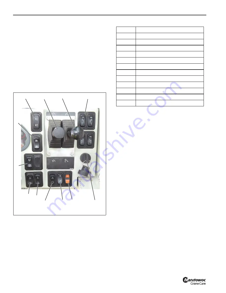
FIGURE 3-4
Right Dash Panel
5
4
1
3
6
7
8
2
9
10
11
12
Item
Description
1
Drum Rotation Indicator (DRI)
2
Hoist Control Lever/DRI Thumb Thumper
3
Boom Lift Control Lever
4
Outrigger/Jack Select Switches
5
Hazard Lights Switch
6
Crane Function Switch
7
Parking Brake Switch
8
Ignition Switch
9
Winch Switch (Optional)
10
360° Swing Lock Switch (Optional)
11
Differential Lock Switch
12
Diesel Exhaust Cleaning Switch
Reference Only
Содержание CD25
Страница 5: ...Operator Manual CD25 R e f e r e n c e O n l y ...
Страница 6: ...R e f e r e n c e O n l y ...
Страница 14: ...TABLE OF CONTENTS CD25 OPERATOR MANUAL TOC 6 THIS PAGE BLANK R e f e r e n c e O n l y ...
Страница 18: ...INTRODUCTION CD25 1 4 Published 1 06 2017 Control 579 01 THIS PAGE BLANK R e f e r e n c e O n l y ...
Страница 55: ...2 37 CD25 SAFETY INFORMATION 2 Published 1 06 2017 Control 579 01 8496 1 FIGURE 2 10 R e f e r e n c e O n l y ...
Страница 66: ...SAFETY INFORMATION CD25 2 48 Published 1 06 2017 Control 579 01 2 48 THIS PAGE BLANK R e f e r e n c e O n l y ...
Страница 100: ...CAPACITY CHART CD25 4 4 Published 1 06 2017 Control 579 01 THIS PAGE BLANK R e f e r e n c e O n l y ...
Страница 150: ...MAINTENANCE CD25 6 40 Published 1 06 2017 Control 579 01 THIS PAGE BLANK R e f e r e n c e O n l y ...
Страница 152: ...ADJUSTMENTS CD25 7 2 Published 1 06 2017 Control 579 01 THIS PAGE BLANK R e f e r e n c e O n l y ...
Страница 156: ...8 4 SPECIFICATIONS CD25 Published 1 06 2017 Control 579 01 Boom angle Maximum 80 Minimum 0 R e f e r e n c e O n l y ...
Страница 159: ...R e f e r e n c e O n l y ...
Страница 160: ...R e f e r e n c e O n l y ...