


3-7
CD25
OPERATING CONTROLS AND PROCEDURES
3
Published 1-06-2017 Control # 579-01
Fuel Gauge
The Fuel Gauge (1) (Figure 3-5) indicates the quantity of fuel
in the fuel tank and has a scale calibrated from 0 (empty) to
4/4 (full). The fuel gauge receives a signal from a sending
unit in the fuel tank.
Left Turn Signal Indicator
The Left Turn Signal Indicator (2) is a green arrow light that
flashes when the turn signal lever is pushed up or the Hazard
Light Switch is positioned to On.
Voltmeter
The Voltmeter (battery gauge) (3) indicates the voltage being
supplied to or from the batteries.
Hourmeter
The hourmeter (4) registers the total hours the engine has
been operating. Use this display to determine when to
perform preventive maintenance.
Diesel Exhaust Fluid (DEF) Level Gauge
The DEF Level Gauge (5) indicates the amount of DEF is in
the DEF tank.
Tachometer
The Tachometer (6) displays engine RPM. The tachometer
receives a signal from the engine ECM.
Right Turn Signal Indicator
The Right Turn Signal Indicator (7) is a green arrow light that
flashes when the turn signal lever is pushed down or the
Hazard Light Switch is positioned to On.
Engine Coolant Temperature Gauge
The Engine Coolant Temperature (water temp) Gauge (8)
indicates the engine coolant temperature on a dual scale
calibrated from 105 to 250°F and 40 to 120°C. The gauge
receives a J1939 signal from the engine ECM and a
temperature sending unit in the engine cooling system.
Crane Function Enabled Indicator
The Crane Function Enabled Indicator (9) illuminates amber
when the crane functions hoist, telescope, boom lift and
swing are activated.
Outrigger Monitoring Indicator
The Outrigger Monitoring Indicator (10) illuminates green
when all the outriggers have been fully extended. The jacks
can be extended to level the crane.
Third Wrap Indicator
The Third Wrap Indicator (11) illuminates red when the wire
rope is down to the last three wraps on the hoist drum.
The
hoist down, telescope out and boom lift functions will be
disabled.
Battery Charge Indicator
With the engine running, the Battery Charge Indicator (12)
illuminates red if battery system voltage is below nine (9)
volts, engine ECM voltage is below nine (9) volts, or there is
no alternator charge signal present.
If the engine is running and the Battery Charge Indicator
illuminates, investigate possible alternator, alternator fuse,
engine drive belt or alternator wiring problems.
When the engine is not running and the Ignition Switch is in
the ACC or RUN position, the Battery Charge Indicator turns
on to indicate the batteries are being drained and not being
charged.
DEF Low Indicator
The DEF Low Indicator (13) illuminates amber when the
level of the exhaust fluid is low.
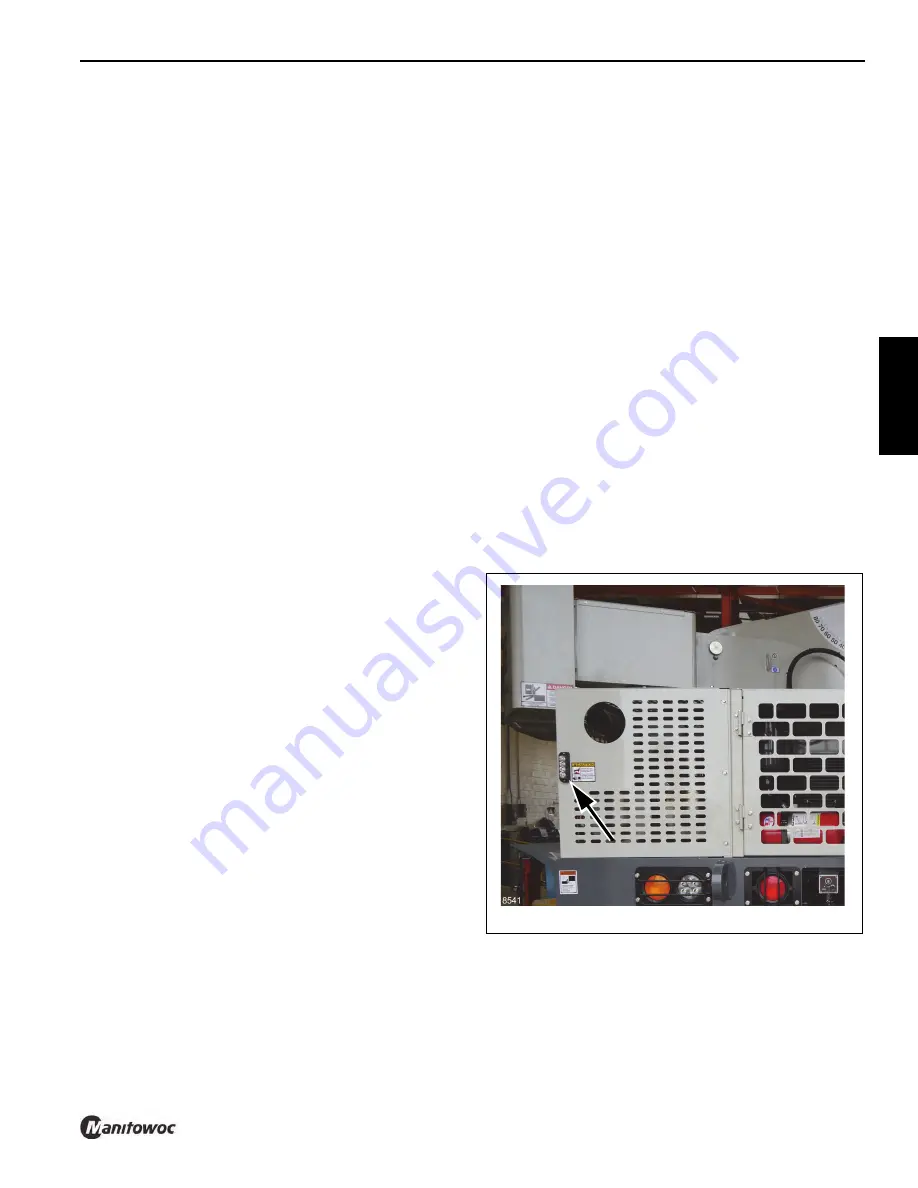
High Exhaust System Temperature (HEST) Indicator
The HEST Indicator (14) illuminates red when the exhaust
temperature is high during exhaust system cleaning. Also a
light (Figure 3-6) by the exhaust pipe will flash as a warning
of high exhaust temperatures.
Inhibit Exhaust System Cleaning Indicator
The Inhibit Exhaust System Cleaning Indicator (15,
Figure 3-5) illuminates amber when the Exhaust System
Cleaning Switch is in the INHIBIT position.
FIGURE 3-6
Reference Only
Содержание CD25
Страница 5: ...Operator Manual CD25 R e f e r e n c e O n l y ...
Страница 6: ...R e f e r e n c e O n l y ...
Страница 14: ...TABLE OF CONTENTS CD25 OPERATOR MANUAL TOC 6 THIS PAGE BLANK R e f e r e n c e O n l y ...
Страница 18: ...INTRODUCTION CD25 1 4 Published 1 06 2017 Control 579 01 THIS PAGE BLANK R e f e r e n c e O n l y ...
Страница 55: ...2 37 CD25 SAFETY INFORMATION 2 Published 1 06 2017 Control 579 01 8496 1 FIGURE 2 10 R e f e r e n c e O n l y ...
Страница 66: ...SAFETY INFORMATION CD25 2 48 Published 1 06 2017 Control 579 01 2 48 THIS PAGE BLANK R e f e r e n c e O n l y ...
Страница 100: ...CAPACITY CHART CD25 4 4 Published 1 06 2017 Control 579 01 THIS PAGE BLANK R e f e r e n c e O n l y ...
Страница 150: ...MAINTENANCE CD25 6 40 Published 1 06 2017 Control 579 01 THIS PAGE BLANK R e f e r e n c e O n l y ...
Страница 152: ...ADJUSTMENTS CD25 7 2 Published 1 06 2017 Control 579 01 THIS PAGE BLANK R e f e r e n c e O n l y ...
Страница 156: ...8 4 SPECIFICATIONS CD25 Published 1 06 2017 Control 579 01 Boom angle Maximum 80 Minimum 0 R e f e r e n c e O n l y ...
Страница 159: ...R e f e r e n c e O n l y ...
Страница 160: ...R e f e r e n c e O n l y ...