


© 2015 Sensata Technologies
Operation
30
4.0 Operation
This section discusses the MMSA inverter/charger’s ON/OFF switch
and LED indicators, explains how the MMSA operates, provides
information on the various remotes (and other accessories) that can
be connected to the unit, and lists the inverter’s/remote’s default
settings.
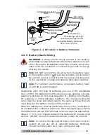
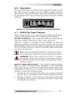
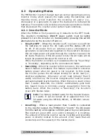
Figure 4-1, Top Panel Power Switch and LED Indicators
4.1 MMSA Top Panel Features
The top panel (Figure 4-1) is used to turn the MMSA on/off and to
monitor its operational status. It is comprised of the following:
ON/OFF Pushbutton
– The momentary pushbutton switch on the
top of the inverter is used to turn the inverter on and off.
When the inverter is connected to the batteries—or when its
automatic protection circuit has turned the inverter off—the ON/
OFF pushbutton switch must be pressed to start the unit. Once the
inverter has been turned on, pressing the ON/OFF switch alternately
turns the unit off and on.
Info:
The power ON/OFF pushbutton is a small momentary
type switch which operates by lightly pressing and releasing.
WARNING:
When any external AC power is passing
through the inverter and is present on the output, pressing
the ON/OFF switch will not remove this AC power on the
inverter’s output.
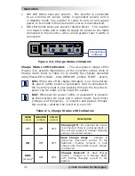
Inverter Status LED Indicator
– The inverter’s status indicator
(INV) is a green LED that provides information on the operational
mode of the inverter. Watch the INV LED status indicator for at least
10 seconds to determine (or to verify) the inverter’s operational
condition—using the information below.
• INV
LED
off
– The inverter is off. There is no AC power from the
inverter, shore, or generator at the inverter’s output terminals.
• INV LED on (solid)
– The inverter is on and using energy from
the battery. The inverter is providing full power to any loads
connected to the inverter.