


© 2015 Sensata Technologies
Installation
16
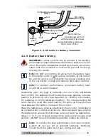
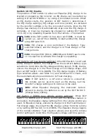
BATTERY
DC cable
with ring lug
bolt
flat washer
nut
lock washer
battery
post
battery terminal
Temperature sensor
(BTS)
Verify that the
DC cable lugs are flush
with the battery terminals.
Torque the battery terminals
from 10 to 12 ft-lbs.
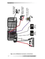
Figure 2-4, DC Cable to Battery Terminals
2.3.5 Battery Bank Wiring
WARNING:
Lethal currents will be present if the positive
and negative cables attached to the battery bank touch each
other. During the installation and wiring process, ensure the
cable ends are insulated or covered to prevent touching/
shorting the cables.
Info:
DO NOT connect the DC wires from the battery bank
to the inverter until: 1) all DC wiring complete, 2) the correct
DC and AC overcurrent protection have been installed, and
3) the correct DC voltage and polarity have been veri
fi
ed.
Info:
For optimum performance, a minimum battery bank
of 200 AH is recommended.
Depending upon the type of batteries you use in the installation
(6 or 12 VDC), the batteries must be wired in series, parallel, or series-
parallel to provide 12 VDC (see Appendix B – Battery Information,
for guidance on wiring batteries together). The interconnecting DC
wires must be sized and rated exactly the same as those that are
used between the battery bank and the inverter.
Place the batteries as close as practical to the inverter, preferably in
an insulated and ventilated enclosure. Allow adequate space above
the batteries to access the terminals and vent caps (as applicable).
Allow
≥
1” (2.5 cm) of space between the batteries to provide good
air
fl
ow. DO NOT mount the batteries directly under the inverter.
Info:
To ensure the best performance from your inverter
system do not use old or untested batteries. Batteries
should be of the same size, type, rating, and age.