


© 2015 Sensata Technologies
Setup
26
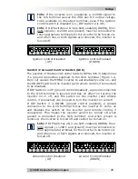
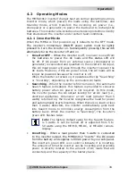
Ground Control Disabled
(UP)
Ground Control Enabled
(DOWN)
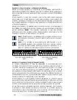
Ignition Control Enabled
(DOWN)
Ignition Control Disabled
(UP)
Info:
If the inverter is on, supplying a +12VDC signal to
the ICS terminal causes the 20A aux DC output voltage
to be available on its output terminal—even if the ignition
control switch is disabled (i.e., DIP Switch 2 is UP).
Info:
If DIP Switches 2 & 3 are both enabled (DOWN), then
both signals (+12VDC and ground) must be connected to
their appropriate terminals for the inverter to be forced on;
and when one or both signals are removed, the inverter is
forced off.
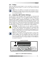
Switch 3:
Ground Control Switch (GCS)
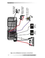
The position of the Ground Control Switch (DIP Switch 3) determines
if a ground connection supplied to the GCS terminal (Figure 1-4,
Item 12) causes the MMSA inverter to automatically come on—and
the ON/OFF switch
on the inverter (and remote control, if connected)
to be disabled.
If DIP Switch 3 is UP (ground control disabled), a ground connection
to the GCS terminal is ignored and has no effect on turning the
inverter on or off, and the switch on the inverter (and remote
control, if connected) can be used to turn the inverter on and off.
If DIP Switch 3 is DOWN (ground control enabled), a ground
connection to the GCS terminal forces the inverter to come on
and disables the switch
on the inverter (and remote control, if
connected). This means the inverter
cannot be turned off when
ground is connected to the GCS terminal; and when ground is
removed, the inverter is forced off and cannot be turned on.
Info:
If DIP Switches 2 & 3 are both enabled (DOWN), then
both signals (+12VDC and ground) must be connected to
their appropriate terminals for the inverter to be forced on;
and when one or both signals are removed, the inverter is
forced off.