


© 2015 Sensata Technologies
Installation
15
according to the size of DC cables being used, which means it is
required to open before the cable reaches its maximum current
carrying capability, thereby preventing a
fi
re. The NEC requires both
overcurrent protection and a disconnect switch.
Because batteries can deliver thousands of amps in an instant during
a short, you are required to install a DC-rated fuse (or circuit breaker)
that has a interrupt current rating (known as Amps Interrupting
Current, or AIC) that can withstand the short-circuit current without
explosion or damage. If a fuse is used as an overcurrent device, a
Class-T type or equivalent is highly recommended when used with
inverters. A Class-T fuse is rated for DC operation, can handle very
high short-circuit currents (up to 100,000 amps), and has a time
delay that allows for momentary current surges from the inverter
without opening the fuse. In some installations, if the combined
short-circuit current of all the batteries in the bank is determined
to be 2,700 amps or less, then an ANL type of fuse may be used—
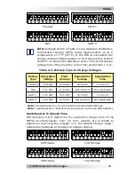
if in doubt, use a Class-T fuse. See Table 2-1 for the fuse size
(coordinated with the DC wire size) recommended for your inverter.
2.3.3 DC Grounding
The inverter should always be connected to a permanent, grounded
wiring system. The idea is to connect the metallic chassis of the
various enclosures together to have them at the same voltage
potential, to reduce the possibility for electric shock. For most
installations, the inverter chassis and the negative battery conductor
are connected to the system’s ground bond via a safety grounding
conductor (bare wire or green insulated wire) at only one point in
the system. The grounding conductor for the DC system shall meet
the sizing requirements speci
fi
ed in the NEC for the application, but
must be no smaller than #8 AWG copper.
For instance: An inverter
used in a marine application under ABYC guidelines requires the size
of the DC grounding conductor to be of an ampacity equal to or one
size less than that of the DC positive conductor.
See Table 2-1 for
the minimum ground wire size recommended for your inverter.
Info:
If the inverter is installed in a vehicle, connect the
battery negative cable directly to the inverter’s negative
terminal. DO NOT connect the negative battery cable meant
for the inverter to the vehicle’s frame/safety ground.
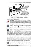
2.3.4 DC Cable Connections
Do not put anything between the battery cable ring lug and the
battery post (see Figure 2-4). When connecting the battery cable,
it should be placed directly against the battery post. Incorrectly
installed hardware causes a high resistance connection which could
lead to poor inverter performance, and may melt the cable and
terminal connections. Torque from 10 to 12 ft-lbs.