


© 2015 Sensata Technologies
Installation
13
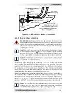
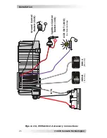
Refer to Figure 2-4 when connecting the DC wires to the battery.
Also, consider the following requirements to ensure maximum
performance:
• The DC positive and negative cables connected to the inverter
from the battery bank should be tied together with wire ties/
straps or electrical tape approximately every 6 inches (15.3
cm). This helps improve the surge capability and reduces the
effects of inductance, which improves the inverter waveform
and reduces the wear of the inverter’s
fi
lter capacitors. Keeping
the battery cables close together also reduces the chance of
radio frequency interference.
• Make sure cables have a smooth bend radius and do not become
kinked. Follow existing wire runs where possible.
• The battery bank voltage MUST be between 9.0-17.0 volts for
the inverter to operate. If the voltage exceeds 17.0V, the inverter
may be damaged.
• To ensure the maximum performance from the inverter, all
connections from the battery bank to the inverter should be
minimized. The exceptions are the DC fuse and disconnect, or
the DC circuit breaker—required at the battery to protect the
DC wiring—in the positive line. Any other additional connection
will contribute to additional voltage drops, and these extra
connection points may loosen during use.
• A brief spark or arc may occur when connecting the battery
cables to the inverter DC terminals; this is normal and due to
the inverter’s internal capacitors being charged.
• Before routing the wiring, color code the DC cables/wires to the
battery bank with colored tape or heat shrink tubing: RED for
positive (+); WHITE for negative (–); and GREEN (or bare copper)
for DC ground, to avoid polarity problems.
• A cable should be connected directly from the inverter negative
terminal to the battery negative connection; this ensures the
inverter has a reliable return path directly to the battery. Do not
use the chassis in place of the battery negative connection to
the inverter.
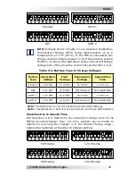
2.3.1 DC Wire Sizing
It is important to use the correct sized DC wire to achieve maximum
ef
fi
ciency from the system and to reduce
fi
re hazards associated
with overheating. Always keep your wire runs as short as practical
to prevent low voltage shutdowns and to keep the DC breaker from
nuisance tripping (or open fuses) because of increased current draw.
See Table 2-1 to select the minimum DC wire size (and corresponding
overcurrent device) required based on your inverter model. The cable
sizes listed in this table are required in order to reduce stress on
the inverter, minimize voltage drops, increase system ef
fi
ciency, and
ensure the inverter’s ability to surge heavy loads.