


Lynx NGT-9000
Installation Manual
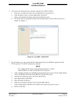
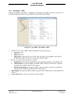
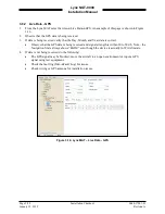
6.
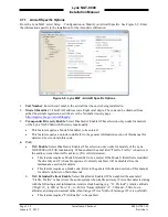
Pilot Entry of Flight ID
: Select Disabled or Enabled.
•
Selecting Enabled provides an entry box at start up.
7.
Aircraft length and Width Code
: Click on the Select button to open a code selection window.
•
Options for No data and from 49.2 up to 295.3.
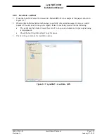
8.
Max Airspeed (knots)
: Enter the maximum allowable airspeed of the aircraft.
9.
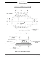
GPS Antenna Offsets (ft)
. (Width offset) The GPS antenna offset indicates the longitudinal distance
between the nose of the aircraft and the GPS antenna and the lateral distance between the
longitudinal center line of the aircraft and the GPS. See AC 20-165A, Appendix 1.
•
GPS Antenna Offset Longitudinal (feet)
. (Length offset) See GPS Antenna Offset Lateral
(feet) above.
•
GPS Antenna Offset Lateral (feet)
. This is to provide the position offset of the GPS antenna
from the ground.
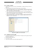
10.
Normal Traffic Color
: Select Cyan or White (default). This selection is used for the panel mount
version of the unit. External displays cannot be configured with this setting.
11.
Click on the Apply button after all information is entered. This information is saved to the
configuration module. Note – The apply button saves all configuration options from each of the
pages.
Page 3-12
Installation Checkout
0040-17001-01
January 15, 2015
Revision A


