

Lynx NGT-9000s
Installation Manual
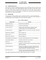
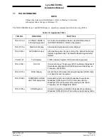
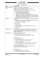
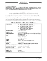
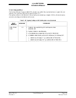
1.10 EQUIPMENT REQUIRED NOT SUPPLIED
Use Table 1-11 to identify equipment required for installation, calibration, and testing.
NOTE
Equivalent tools, equipment and hardware may be used.
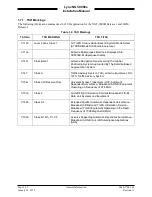
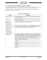
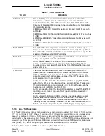
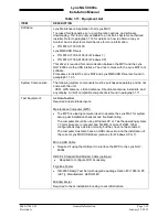
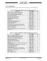
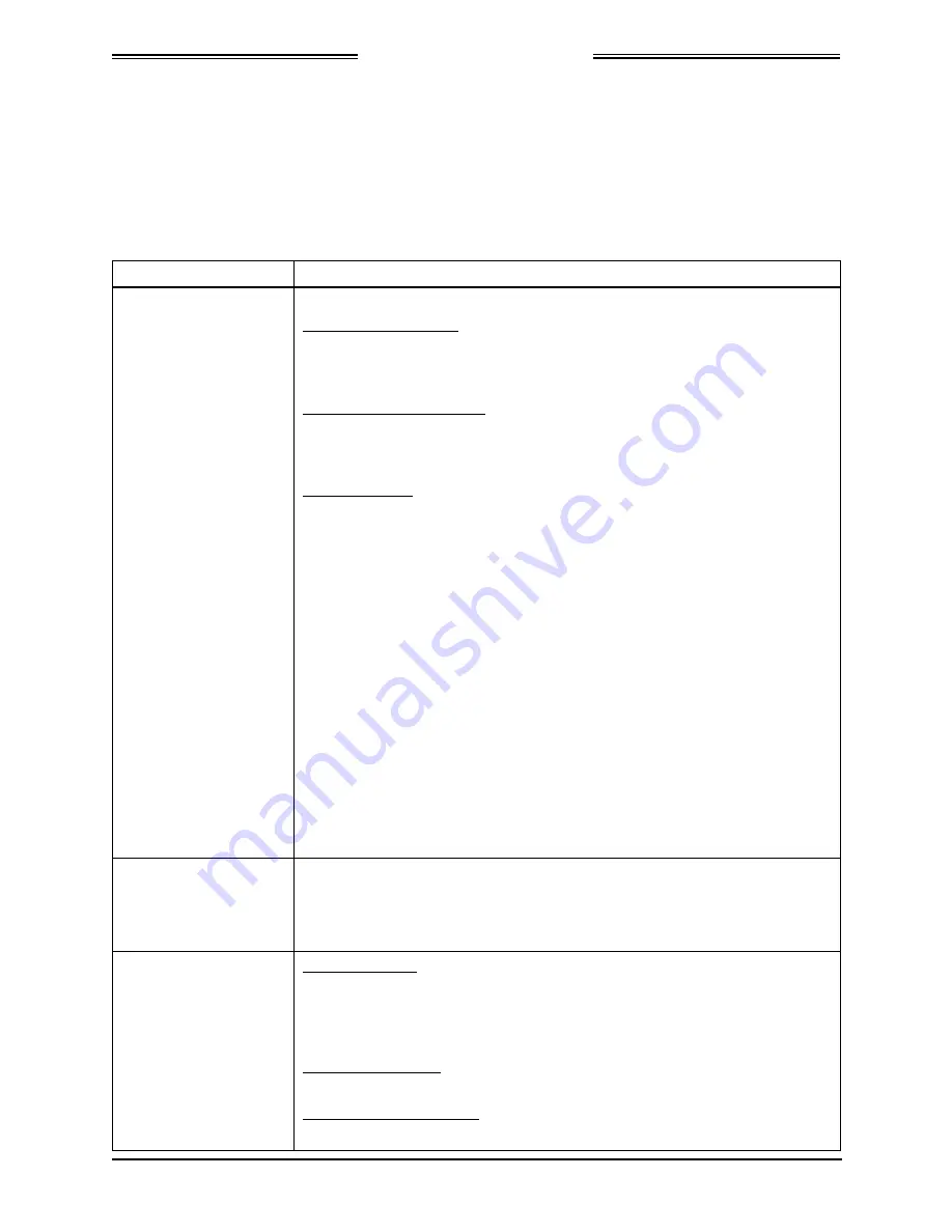
Table 1-11: Equipment List
ITEM
DESCRIPTION
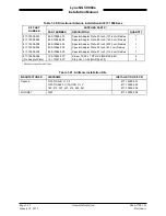
Cables and Wiring:
The installer supplies all system wires and cables.
Mating Connector (P1)
•
Wires are #22 or #24 AWG as noted on interconnect wiring diagram in
section 2. Use M22759 or equivalent wire and use M27500 or equivalent
for twisted shielded wire for installation.
WiFi Accessory Connector
•
9-Pin Sub-D Connector, P/N M24308/2-1 or equivalent. Use M27500 or
equivalent for twisted shielded wire for installation as noted on
interconnect wiring diagram.
Antenna Cables
•
L-Band and GPS Antenna
Require M17/128-RG400 or equivalent coaxial cable. For the L-Band
antenna the attenuation must not exceed 1.5 dB per cable (including the
connectors). For the GPS antenna the attenuation should not exceed 10
dB per cable (including the connectors).
NOTE
RG type coaxial cable insertion loss can vary significantly between
manufacturers. Refer to the cable manufacturer's specification sheet
for actual attenuation (insertion loss) for the cable being used.
•
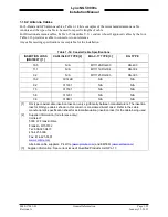
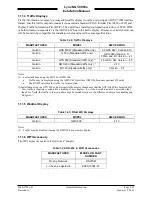
Directional Antenna (Required only for models with TAS)
The Directional Antenna (NY156 or NY164) requires three cable
assemblies; sum (Sigma Port), bit probe (Probe Port) and difference
(Delta Port). Cable attenuation for the sum and difference ports must not
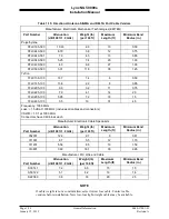
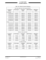
exceed 1.5 dB. Table 1-15 identifies U. S. vendors who sell approved
cables by the foot. Table 1-16 provides a cable to connector cross-
reference.
M17/128-RG-400 or equivalent may be used for the bit probe cable.
Attenuation for the bit probe cable must not exceed 6 dB.
Circuit Breaker:
Installer is responsible for determining appropriate circuit breakers needed to
protect aircraft wiring. Manufacturer recommends the following:
•
2.0 Amp circuit breaker for the unit with 28Vdc input
•
5.0 Amp circuit breaker for the unit with 14Vdc input
Consumables:
Antenna Sealant
•
For pressurized aircraft, use a sealant that meets the requirements of
SAE AMS-S-8802 such as Flamemaster® CS3204 class B. For non-
pressurized aircraft, use a non-corrosive sealant that meets the physical
requirements of MIL-A-46146 such as General Electric RTV162.
Surface Preparation
•
Alodine® No. 1001 required for installation of the antenna.
Tie Wraps or Lacing Cord
•
Commercially available.
0040-17001-01
General Information
Page 1-21
Revision A
January 15, 2015


