


Lynx NGT-9000s
Installation Manual
4.3.2 Directional Antenna (NY156 and NY164)
CAUTION
Do not paint the antennas. Do not use cleaning solvents on the
antennas.
•
Check for dents, cracks, and punctures.
•
Remove all dirt and grease from surface areas. Clean with a soft cloth moistened with mild soap and
water.
•
Visually inspect sealant around the antenna base. Reapply sealant if required.
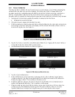
4.4 FAULT ISOLATION
Use the following information for initial installations and debugging issues that may appear during
operation.
Use Table 4-1 to view observed failures or conditions and possible cause and corrective actions. The
symptoms listed are for all the possible equipment installations. It is up to the user to identify their
particular installation.
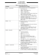
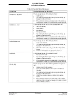
Use Table 4-2 to review system status messages that may be seen on the screen during start up or when
the system test button is pressed.
NOTE
The information listed in the Symptoms column encompass all the
possible issues that a technician may observe, but only some of the items
may actually be seen depending on model options and secondary
equipment being used.
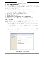
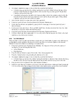
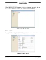
A MPC connected to the USB port of the Lynx NGT-9000s is essential in troubleshooting. Refer to
paragraph 4.5.3.2 (list of fault log messages) and
Table 4-3
for instructions on viewing fault logs and using
the service functions of the Lynx MAT. The information provided here should be in conjunction with the
information provided in
Table 4-1
and
Table 4-2
.
It should be noted that the ADS B Out Fail Lamp will be ON when the unit is in maintenance mode (via
the Lynx MAT).
If the only corrective action left is to contact L 3 Field Service, then L 3 Field service personnel may
request that a file be created using the MPC that would provide them with information on the unit (i.e.
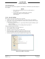
version, faults, and configuration). Create this file by going to the File menu of the Lynx MAT, selecting
Save, and placing the file in a location that can be easily located for transfer to L 3 Field Service.
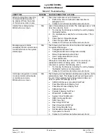
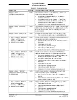
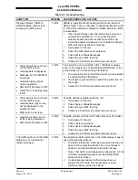
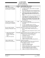
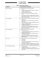
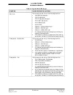
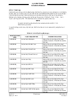
Table 4-1: Troubleshooting
SYMPTOM
SCREEN CAUSE/CORRECTIVE ACTIONS
Blank display.
All
Loss of power or damaged unit.
1. Check power connections, breakers, and main
avionics switch.
2. Verify Battery (BAT) Master switch is on.
3. Check the Lynx MAT fault log.
4. Contact L-3 Field Service before removal of unit.
The unit has manual
brightness adjustment only.
All
Loss of light sensor data.
1. Try clearing the failure by restarting the unit by tapping
the Restart button.
2. Check System Status Messages.
3. Check the Lynx MAT fault log.
4. Contact L-3 Field Service before removal of unit.
0040-17001-01
Maintenance
Page 4-3
Revision A
January 15, 2015


