


Lynx NGT-9000s
Installation Manual
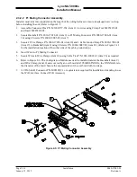
3.
Apply Heating on the Solder Sleeve
a.
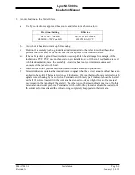
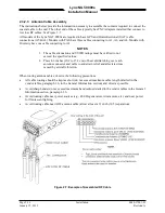
Use Tyco Electronics approved heat source and reflector as shown below:
Heat Gun / Setting
Reflector
HL1910E = 6 on dial
HL2010E = 700°F on LCD
PR-25 or PR-25D and
HL1802E-ADAPT
b.
Allow hot air heaters to warm up before using.
c.
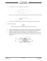
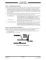
Position the assembly (cable, ground lead and terminator) in the reflector so that the solder
preform is in the center of the hot air or at the focal point on the infrared heaters.
d.
If the cable jacket or ground lead insulation is susceptible to heat damage for example, if the
insulation is PVC (PVC may not be used on new installations), or if the infrared heating is used
with black insulation, move the assembly toward the heat source to minimize unwanted
exposure of the jacket to the heat.
e.
Heat until the solder preform melts flows and wets the shield and ground lead.
f.
Some terminators contain a thermal indicator to signal when the correct amount of heat has been
applied to the solder. There are two types of indicators. One is a thermo-chromic material which
signals correct heating by loss of color. Terminators with this type of indicator should be heated
until all the colored material in the joint area has turned colorless. (Slight traces of the material
may remain in the standing of the shield). The other type of thermal indicator is a ring of fusible
material around solder preform. Terminators with this Bi-Alloy indicator should be heated until
the solder preform melts and the indicator ring completely disappears in the joint area.
0040-17001-01
Installation
Page 2-9
Revision A
January 15, 2015


