


Lynx NGT-9000s
Installation Manual
Section 4
Maintenance
4.1 INTRODUCTION
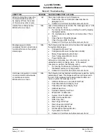
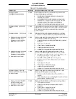
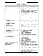
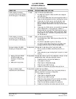
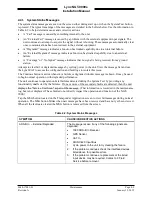
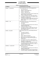
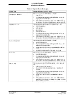
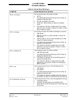
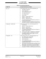
This chapter contains general flightline maintenance and fault isolation procedures. Fault isolation is
intended to aid in identifying and correcting invalidities or isolating failures to a defective assembly.
4.2 CONTINUED AIRWORTHINESS
Regular maintenance of the Lynx NGT-9000s is not required except as included in this section and is to
be maintained on a “Condition Monitored” basis. Condition monitoring is based upon the following:
•
Visual observation by the user.
•
All units have unlimited service life, where service life is defined as that point in time when repair is
no longer economical.
The unit is subject to the following requirements:
•
Title 14 CFR Part 91.411 (Altimeter)
•
Title 14 CFR Part 91.413 (Transponder)
•
Title 14 CFR Part 43 Appendix E & F
The Directional Antennas (NY156 or NY164) do not require scheduled maintenance or scheduled
overhaul and shall be maintained on a “Condition Monitored” basis.
4.3 PERIODIC MAINTENANCE
Perform the following at regular aircraft inspection intervals:
•
Visually inspect for signs of corrosion.
•
Visually Inspect for condition of wiring, shield terminations for proper grounding, routing, and
attachment/clamping.
•
Visually inspect the unit mounting to the aircraft, verify visually that the screw heads are in full
contact with the mounting holes etc. Re-torque the screws if required.
•
Check the display for cleanliness. The bezel, ambient light sensor, and display glass can be cleaned
with a damp lint-free, static-free cloth. If necessary, clean with a soft cloth moistened with a mild
solution of soap and water. Care should be taken to avoid scratching the surface of the display or
getting water inside the USB maintenance port. Do not spray cleaner directly on the screen.
•
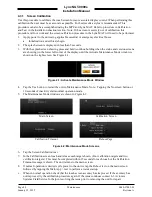
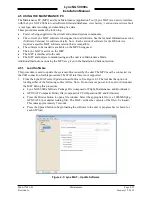
If the touch screen does not respond to a tap in the right location perform the screen calibration in
paragraph 4.3.1.
•
It is recommended that an electrical bond check be performed between the unit and nearby exposed
portion of the aircraft metallic structure and verify that the measured value is less than or equal to 2.5
milliohms.
In the event of bonding check failure, remove the unit and clean it and its mounting holes at both the
unit and the aircraft structure and reattach the unit. Re-verify the resistance between the unit and
nearby exposed portion of aircraft metallic structure, and ensure it is less than or equal to 2.5
milliohms.
0040-17001-01
Maintenance
Page 4-1
Revision A
January 15, 2015


