Chapter 12. TROUBLE SHOOTING
12 - 5
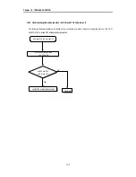
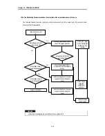
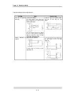
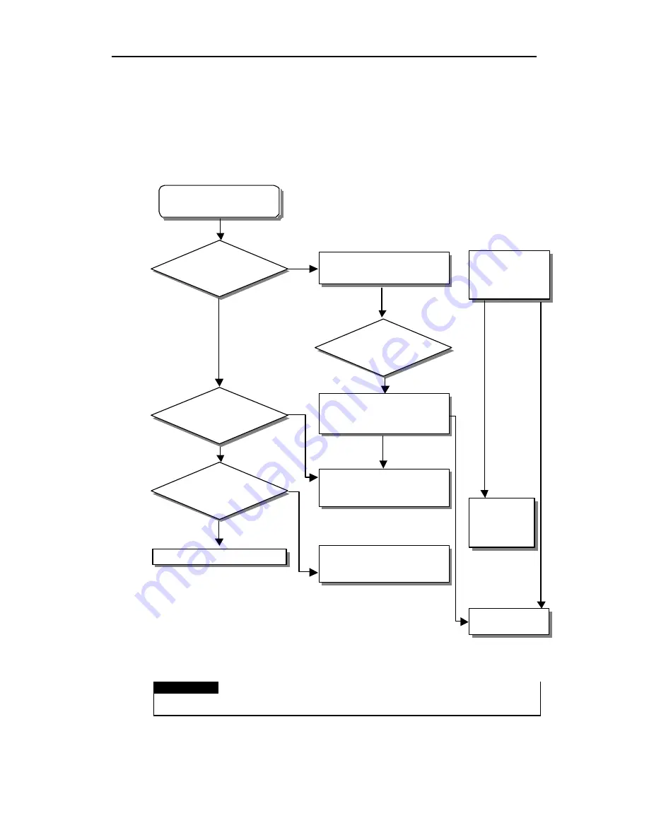
12.2.4 Troubleshooting flowchart used when the output load of the output module does not turns on.
The following flowchart explains corrective action procedure used when the output load of the output module
does not turn ON during operation
REMARK
1) If the input or load signals are not switched OFF, see Section 12.4.1
Output load does not turn
ON.
Is the indicator LED of the
output module ON
Check the output status in monitor
mode of the peripheral devices
Yes
Is the voltage of power
supply for load applied?
Is the voltage of power
supply for load applied?
Output module defect
Is the indicator LED Of the
input module ON
Check the input signal OFF in
monitor mode with the peripheral
devices
Check the wiring load of the power
supply for load and restore the
power
Check the wiring load of the power
supply for load and restore the
power
Measure the voltage
across module input
terminal and CPU
terminal
Check external
wiring and
external input
equipment
Contact the nearest
service center
Yes
No
No
Содержание GLOFA GM6 Series
Страница 1: ...U s e r s M a n u a l LG Programmable Logic Controller GLOFA GM6 Series L G Industrial Systems ...
Страница 2: ... CONTENTS ...
Страница 178: ...Chapter 15 The PID functions 15 24 Example program of 15 4 3 1 ...
Страница 179: ...Chapter 15 The PID functions 15 25 Example program of 15 4 3 2 continue to next page ...
Страница 180: ...Chapter 15 The PID functions 15 26 Example program of 15 4 3 2 continued ...
Страница 209: ...Appendix 4 Outer Dimensions APP4 3 ...

