Appendix 2. Flag List
APP2 - 3
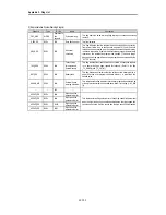
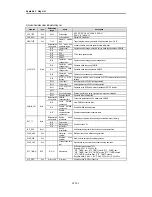
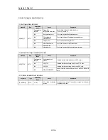
4) Detailed System Error and Warning Flag List
Keyword
Type
Data setting
range
Name
Description
_IO_TYER_N
UINT
0 to 15
The number of slot
whose module type is
inconsistent.
This flag detects that I/O configuration parameters of each slot differ
from the real loaded module configuration or a particular module is
loaded onto the slot where modules cannot be loaded, and indicates
the lowest slot No. of the detected slot numbers.
_IO_TYERR[n]
BYTE
n: 0 to 1
The location of slot
where module type is
inconsistent.
This flag detects that I/O configuration parameters of each slot differ
from the real loaded module configuration or a particular module is
loaded onto the slot where modules cannot be loaded, and indicates
the slot locations in the bit map of base units.
_IO_DEER_N
UINT
0 to 15
The number of slot
where module
mounting/dismounting
error occurred.
This flag detects that module configuration of each slot has been
changed, that is, module mounting/dismounting error has been
occurred, and indicates the lowest slot No. of the detected slot
numbers.
_IO_DEERR[n]
BYTE
n: 0 to 1
The location of slot
where module
mounting/dismounting
error occurred.
This flag detects that module configuration of each slot has been
changed, that is, module mounting/dismounting error has been
occurred, and indicates the slot locations in the bit map of base
units.
_FUSE_ER_N
UINT
0 to 15
The number of slot
where fuse breaks.
This flag detects that fuses of fuse-mounted modules has broken,
and indicates the lowest slot No. of the detected slot numbers.
_FUSE_ERR[n]
BYTE
n: 0 to 1
The location of slot
where fuse breaks.
This flag detects that fuses of fuse-mounted modules has broken,
and indicates the slot locations in the bit map of base units.
_IO_RWER_N
UINT
0 to 15
The number of slot
where I/O module
read/write occurred.
This flag detects that input modules of a slot cannot be normally
read from or written to, and indicates the lowest slot No. of the
detected slot numbers.
_IO_RWERR[n]
BYTE
n: 0 to 1
The location of slot
where I/O module
read/write occurred.
This flag detects that input modules of a slot cannot be normally
read from or written to, and indicates the slot locations in the bit map
of base units.
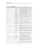
_IP_IFER_N
UINT
0 to 15
Special/link module
interface error slot No.
This flag detects that initialization cannot be executed for special or
link module of a slot, or normal interface is impossible due to module
malfunction, and indicates the lowest slot No. of the detected slot
numbers.
_IP_IFERR[n]
BYTE
n: o to 1
Special/link module
interface error location
This flag detects that initialization cannot be executed for special or
link module of a slot, or normal interface is impossible due to module
malfunction, , and indicates the slot locations in the bit map of base
units.
_ANC_ERR[n]
UINT
n : 0 to 7
External device fatal
error
This flag detects fatal error of external devices and its content is
written to this flag. A number that identifies error type will be written
to each of the sixteen locations. (The number 0 is not allowed)
_ANC_WAR[n]
UINT
n : 0 to 7
External device
ordinary error
If the user program indicates a warning on the flag _ANC_WB[n], the
bit locations are sequentially written to _ANC_WAR[n] from
_ANC_WAR[0] complying with their occurrence sequence.
_ANC_WB[n]
BIT
n: 0 to 127
External device
ordinar y error bit map
The user program detects ordinary error of external device and the
errors are indicated on a bit map. (The number 0 is not allowed)
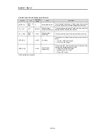
_TC_BMAP[n]
BIT
n : 0 to 7
Task collision bit map
The flag detects that task collision has occurred because, while a
task was being executed or ready for execution, an execution
request has occurred for the same task, indicates the errors on a bit
map.
_TC_CNT[n]
UINT
n : 0 to 7
Task collision counter
This flag detects task collision occurrence time for each task when
executing a user program, indicates the task collision occurrence
time.
Содержание GLOFA GM6 Series
Страница 1: ...U s e r s M a n u a l LG Programmable Logic Controller GLOFA GM6 Series L G Industrial Systems ...
Страница 2: ... CONTENTS ...
Страница 178: ...Chapter 15 The PID functions 15 24 Example program of 15 4 3 1 ...
Страница 179: ...Chapter 15 The PID functions 15 25 Example program of 15 4 3 2 continue to next page ...
Страница 180: ...Chapter 15 The PID functions 15 26 Example program of 15 4 3 2 continued ...
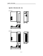
Страница 209: ...Appendix 4 Outer Dimensions APP4 3 ...

