Chapter 1. INTRODUCION
1 - 4
Terms
Definition
Remarks
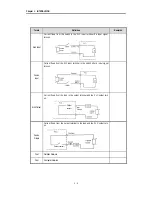
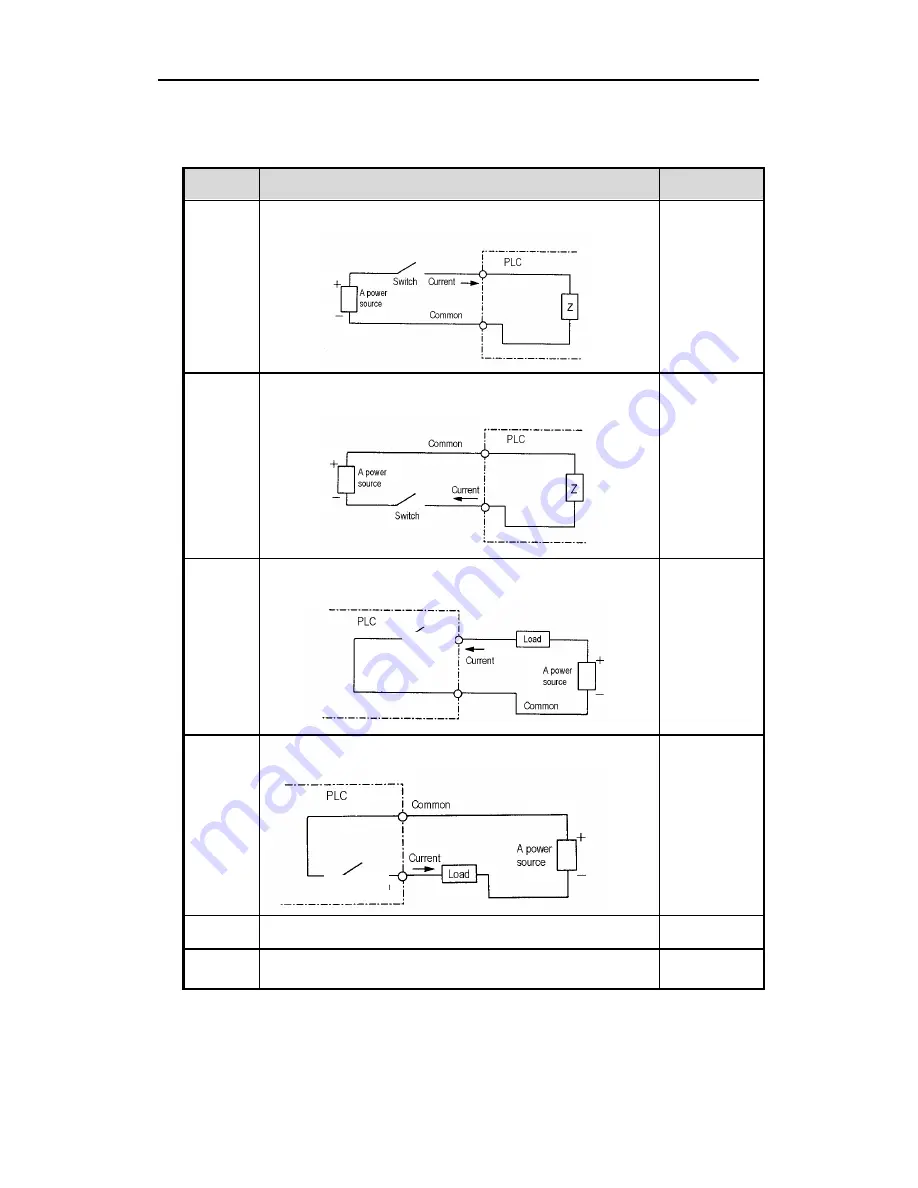
Sink Input
Current flows from the switch to the PLC input terminal if a input signal
turns on.
Source
Input
Current flows from the PLC input terminal to the switch after a input signal
turns on.
Sink Output
Current flows from the load to the output terminal and the PLC output turn
on.
Source
Output
Current flows from the output terminal to the load and the PLC output turn
on.
Fnet
Fieldbus Network
Cnet
Computer Network
Output
contact
Output contact
Содержание GLOFA GM6 Series
Страница 1: ...U s e r s M a n u a l LG Programmable Logic Controller GLOFA GM6 Series L G Industrial Systems ...
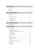
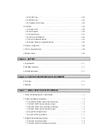
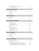
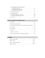
Страница 2: ... CONTENTS ...
Страница 178: ...Chapter 15 The PID functions 15 24 Example program of 15 4 3 1 ...
Страница 179: ...Chapter 15 The PID functions 15 25 Example program of 15 4 3 2 continue to next page ...
Страница 180: ...Chapter 15 The PID functions 15 26 Example program of 15 4 3 2 continued ...
Страница 209: ...Appendix 4 Outer Dimensions APP4 3 ...


