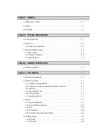
4.4.3 PAUSE mode
······················································································································
4 - 25
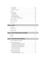
4.4.4 DEBUG mode
·····················································································································
4 - 25
4.4.5 Operation Mode Change
····································································································
4 - 26
4.5 Functions
·····································································································································
4 - 28
4.5.1 Restart mode
······················································································································
4 - 28
4.5.2 Self-diagnosis
·····················································································································
4 - 30
4.5.3 Remote function
·················································································································
4 - 31
4.5.4 I/O Force On/Off function
···································································································
4 - 32
4.5.5 Direct I/O Operation function
······························································································
4 - 33
4.5.6 External Device Error Diagnosis function
··········································································
4 - 33
4.6 Memory Configuration
·················································································································
4 - 36
4.7 I/O No. Allocation Method
············································································································
4 - 38
4.8 Names of Parts
····························································································································
4 - 39
Chapter 5. BATTERY
5.1 Specifications
································································································································
5 - 1
5.2 Handling Instructions
····················································································································
5 - 1
5.3 Battery Replacement
····················································································································
5 - 1
Chapter. 6 USING THE USER PROGRAM IN FLASH MEMORY
6.1 Structure
·······································································································································
6 - 1
6.3 Handling
······································································································································
6 - 1
Chapter. 7 DIGITAL INPUT AND OUTPUT MODULES
7.1 Notes on Selecting Input and Output Modules
·············································································
7 - 1
7.2 Digital Input Module Specifications
·······························································································
7 - 2
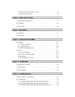
7.2.1 16-point 24VDC input module (source/sink type)
·······························································
7 - 2
7.2.2 16-point 24VDC input module (source type)
·······································································
7 - 3
7.2.3 32-point 24VDC input module (source/sink type)
·······························································
7 - 4
7.2.4 32-point 24VDC input module (source type)
·······································································
7 - 5
7.2.5 8-point 110VAC input module
····························································································
7 - 6
7.2.6 8-point 220VAC input module
······························································································
7 - 7
7.3 Digital Output Module Specifications
····························································································
7 - 8
7.3.1 16-point relay output module
·······························································································
7 - 8
7.3.2 16-point transistor output module (sink type)
······································································
7 - 9
Содержание GLOFA GM6 Series
Страница 1: ...U s e r s M a n u a l LG Programmable Logic Controller GLOFA GM6 Series L G Industrial Systems ...
Страница 2: ... CONTENTS ...
Страница 178: ...Chapter 15 The PID functions 15 24 Example program of 15 4 3 1 ...
Страница 179: ...Chapter 15 The PID functions 15 25 Example program of 15 4 3 2 continue to next page ...
Страница 180: ...Chapter 15 The PID functions 15 26 Example program of 15 4 3 2 continued ...
Страница 209: ...Appendix 4 Outer Dimensions APP4 3 ...


