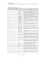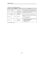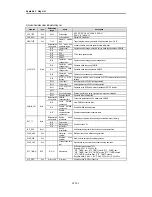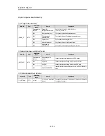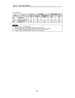
Appendix 2. Flag List
APP2 - 6
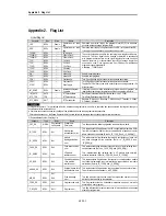
6) System Configuration status Information Flag
(1) User Program Status Information
Keyword
Type
Data setting
range
Name
Description
Representative
keyword
System S/W
configuration information
GM1 : 0, GM2 : 1, (GM3 : 2, GM4 : 3, GM% : 4)
(FSM : 5,6), Twofold : 16
Bit 0
Basic parameter error
Checks and indicates Basic parameter error
Bit 1
I/O configuration
parameter error
Checks and indicates I/O configuration parameter error
Bit 2
Program error
Checks and indicates Program error
Bit 3
Access variable error
Checks and indicates Access variable error
_DOMAN_ST
BYTE
Bit 4
High speed link
parameter error
Checks and indicates High speed link parameter error
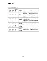
(2) Operation Mode change switch Status Information
Keyword
Type
Data Setting
range
Name
Description
Representative
keyword
Mode setting switch
position
Indicates the state mode setting switch of CPU module
Bit 0
KEY_STOP
Indicates that the mode setting switch is in the STOP state.
Bit 1
KEY_RUN
Indicates that the mode setting switch is in the RUN state.
_KEY_STATE
BYTE
Bit 2
KEY_PAUSE/REMOTE
Indicate s that the mode setting switch is in the PAUSE/REMOTE
state.
(3) I/O Module Installation Status Information
Keyword
Type
Data Setting
range
Name
Description
_IO_INSTALL[n]
BYTE
n : 0 to 1
I/O module installation
location
Locations of slots where I/O modules are loaded are indicated in
the bitmap of base units.
Содержание GLOFA GM6 Series
Страница 1: ...U s e r s M a n u a l LG Programmable Logic Controller GLOFA GM6 Series L G Industrial Systems ...
Страница 2: ... CONTENTS ...
Страница 178: ...Chapter 15 The PID functions 15 24 Example program of 15 4 3 1 ...
Страница 179: ...Chapter 15 The PID functions 15 25 Example program of 15 4 3 2 continue to next page ...
Страница 180: ...Chapter 15 The PID functions 15 26 Example program of 15 4 3 2 continued ...
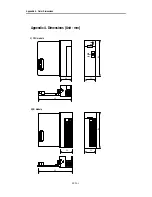
Страница 209: ...Appendix 4 Outer Dimensions APP4 3 ...

