Chapter 10. INSTALLATION AND WIRING
10 - 11
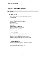
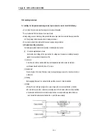
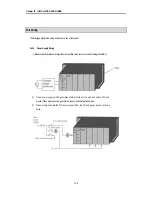
10.2.2 Input and Output Devices Wiring
1) Applicable size of wire for I/O wiring is 0.3 to 2 mm
2
. However, it is recommended to use wire of 0.3mm
2
for
convenience.
2) Separate the input and output lines.
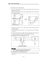
3) I/O signal wires must be at least 100 mm away from high voltage and large current main circuit wires.
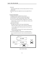
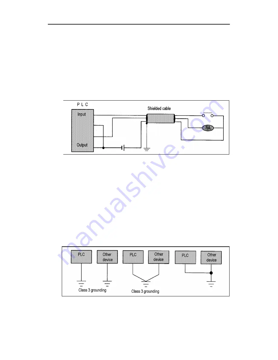
4) When the I/O signal wires cannot be separated from the main circuit wires and power wires, ground on the
PLC side with batch-shielded cables.
5) If wiring has been done with a piping, ground the piping.
6) Separate the 24 VDC I/O cables from the 110 VAC and 220 VAC cables.
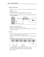
7) If wiring over 200 m or longer distance, problems can be caused by leakage currents due to line capacity.
Refer to the Section 12.4 Examples.
10.2.3 Grounding
1) This PLC has sufficient protection against noise, so it can be us ed without grounding except for special
much noise. However, when grounding it should be done conforming to below items.
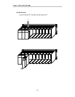
2) Ground the PLC as independently as possible. Class 3 grounding should be used (grounding resistance
100
Ω
or less).
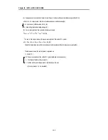
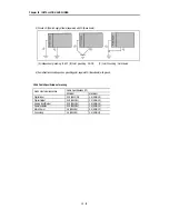
3) When independent grounding is impossible, use the joint grounding method as shown in the figure below (B).
(A) Independent grounding : Best (B) Joint grounding : Good (C) Joint grounding : Not allowed
4) Use 2 mm
2
or more wire for grounding line. Make the distance as short as possible with the grounding point
located to nearest to the PLC.
Содержание GLOFA GM6 Series
Страница 1: ...U s e r s M a n u a l LG Programmable Logic Controller GLOFA GM6 Series L G Industrial Systems ...
Страница 2: ... CONTENTS ...
Страница 178: ...Chapter 15 The PID functions 15 24 Example program of 15 4 3 1 ...
Страница 179: ...Chapter 15 The PID functions 15 25 Example program of 15 4 3 2 continue to next page ...
Страница 180: ...Chapter 15 The PID functions 15 26 Example program of 15 4 3 2 continued ...
Страница 209: ...Appendix 4 Outer Dimensions APP4 3 ...


