Chapter 10. INSTALLATION AND WIRING
10 - 2
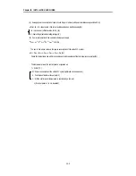
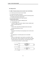
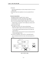
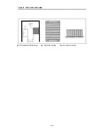
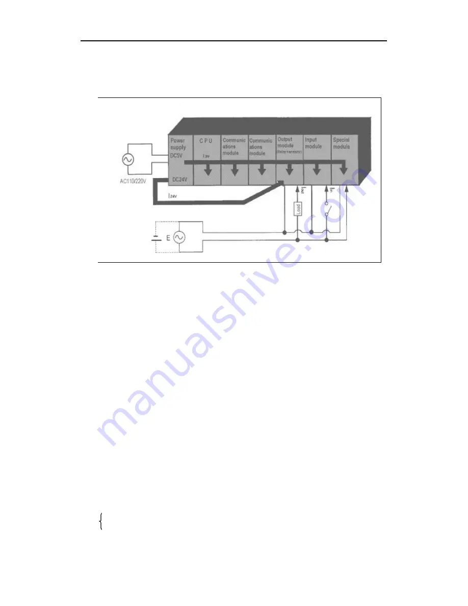
The following shows the procedure for calculating the PLC system power consumption.
1) PLC system power consumption block diagram
2) Power consumption of each part
(1) Power consumption of a power supply module
Approximately 70% of the power supply module current is converted into power and 30% of that 70%
dissipated as heat, i.e., 3/7 of the output power is actually used.
•
Wpw = 3/7 {(I
5V
×
5)
+
(I
24V
×
24)} (W)
where, I
5V
= 5 VDC circuit current consumption of each module
I
24V
= 24 VDC circuit average current consumption of output modules (with points
simultaneously switched ON). Not for 24 VDC power supplied from external or power
supply modules that has no 24 VDC output.
(2) Total 5 VDC power consumption
The total power consumption of all modules is the power of the 5 VDC output circuit of the power supply
module.
•
W
5V
= I
5V
×
5 (W)
(3) Average 24 VDC power consumption (with points simultaneously switched ON)
The total power consumption of all modules is the average power of the 24 VDC output circuit of the power
supply module.
•
W
24V
= I24
V
×
24 (W)
(4) Average power consumption by voltage drop of output modules (with points simultaneously switched ON)
•
Wout = Iout
×
Vdrop
×
output points
×
the rate of points switched on simultaneously (W)
Iout : output current (actual operating current) (A)
Vdrop : voltage dropped across each output load (V)
Содержание GLOFA GM6 Series
Страница 1: ...U s e r s M a n u a l LG Programmable Logic Controller GLOFA GM6 Series L G Industrial Systems ...
Страница 2: ... CONTENTS ...
Страница 178: ...Chapter 15 The PID functions 15 24 Example program of 15 4 3 1 ...
Страница 179: ...Chapter 15 The PID functions 15 25 Example program of 15 4 3 2 continue to next page ...
Страница 180: ...Chapter 15 The PID functions 15 26 Example program of 15 4 3 2 continued ...
Страница 209: ...Appendix 4 Outer Dimensions APP4 3 ...


