Chapter 10. INSTALLATION AND WIRING
10 - 10
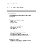
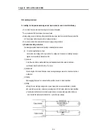
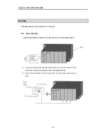
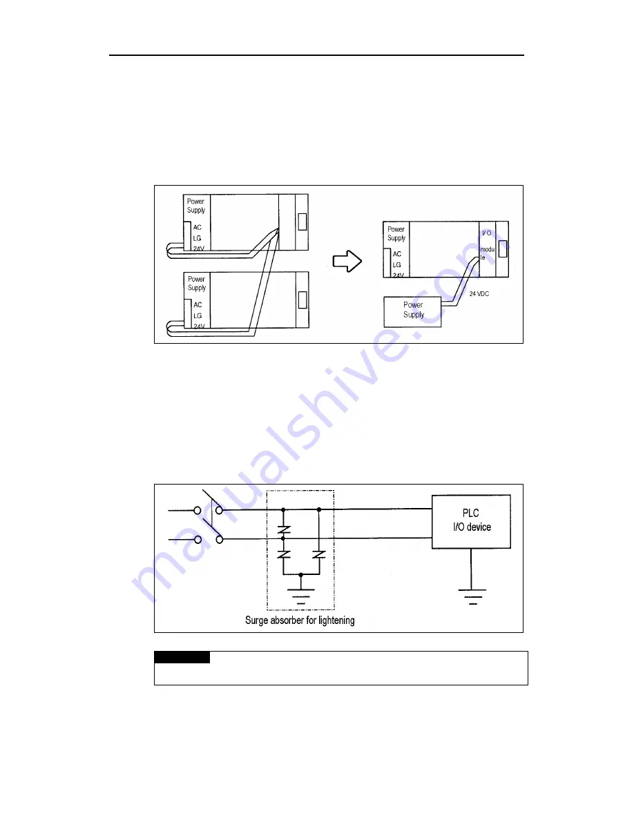
4) Notes on using 24 VDC output of the power supply module
•
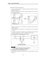
To protect the power supply modules, do not supply one I/O module with 24 VDDC from several power
supply modules connected in parallel.
•
If 24 VDC output capacity is sufficient for one power supply module, supply 24 VDC from the external 24
VDC power supply as shown below.
5) Twist the 110 VAC, 220 VAC, and 24 VDC cables as closely as possible. Connect modules with the
shortest possible wire lengths.
7) To minimize voltage drop, use the thickest (max. 2 mm
2
) wires possible for the 100 VAC, 200VAC and
24 VDC cables.
8) Do not bundles the 100 VAC and 24 VDC cables with main-circuit(high voltage, large current) wires or
the I/O signal wires. If possible, provide more than 100 mm distance between the cables and wires.
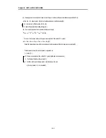
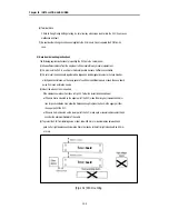
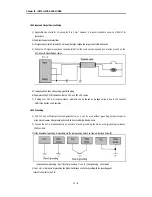
8) As a lightning-protection measure, connect a surge absorber as shown below.
REMARK
1) Ground the surge absorber (E1) and the PLC(E2) separately from each other.
2) Select a surge absorber making allowances for power voltage rises.
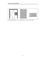
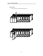
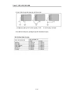
9) Use a insulating transformer or noise filter for protection against noise .
10) Twist every input power supply wires as closely as possible. Do not allow the transformer or noise filter
across the duct.
Содержание GLOFA GM6 Series
Страница 1: ...U s e r s M a n u a l LG Programmable Logic Controller GLOFA GM6 Series L G Industrial Systems ...
Страница 2: ... CONTENTS ...
Страница 178: ...Chapter 15 The PID functions 15 24 Example program of 15 4 3 1 ...
Страница 179: ...Chapter 15 The PID functions 15 25 Example program of 15 4 3 2 continue to next page ...
Страница 180: ...Chapter 15 The PID functions 15 26 Example program of 15 4 3 2 continued ...
Страница 209: ...Appendix 4 Outer Dimensions APP4 3 ...


