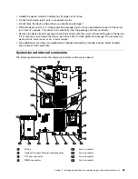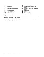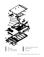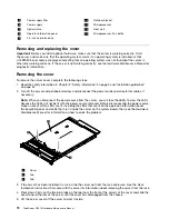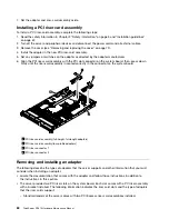
– A PCI Express riser card assembly has a black connector and supports PCI Express adapters.
– PCI riser slot 1 (this slot is the farthest slot away from the power supplies). This slot supports only
low-profile adapters.
– PCI riser slot 2 (this slot is the closest slot to the power supplies). This slot supports only full-height,
half-length adapters.
• Do no set the maximum digital video adapter resolution above 1600 x 1200 at 60 Hz for an LCD monitor.
This is the highest resolution that is supported for any add-on video adapter that you install in the server.
• Any high-definition video-out connector or stereo connector on any add-on video adapter is not
supported.
• The server does not support full-length adapters.
• When you install any PCI adapter, the power cords must be connected form the power source before
you remove the PCI Express riser-card assembly. Otherwise, the active power management event
signal will be disabled by the system-board logic, and the WAN feature might not work. However, after
the server is powered on locally, the active power manager active power management event signal will
be enabled by the system-board logic.
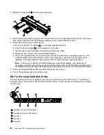
• If you switch the PCI adapter from slot 1 riser assembly to slot 2, you will need to remove the screw from
the standard bracket and then replace the standard bracket with the low-profile bracket.
• The server provides two PCI riser-card slots
• To install any PCI adapter, both the AC and DC power cords must be disconnected from the power
source before you remove the PCI Express riser assembly. Otherwise, this will cause the active power
management event signal to become disabled by hardware. However, after the server is powered-on
locally, the active power manager active power management event signal will be enabled by hardware.
Removing an adapter
To remove an adapter, complete the following steps:
1. Read the safety information in Chapter 2 “Safety information” on page 3 and “Installation guidelines”
on page 67.
2. Turn off the server and peripheral devices and disconnect all power cords; then, remove the cover (see
“Removing and replacing the cover” on page 72).
3. Disconnect any cables from the adapter.
4. Grasp the riser-card assembly at the rear edge and lift to remove the riser-card assembly.
5. Place the riser-card assembly on a flat, static-protective surface.
6. Carefully grasp the adapter by its top edge or upper corners, and pull the adapter from the riser-card
assembly.
Chapter 7
.
Installing optional devices and replacing customer replaceable units
83
Содержание ThinkServer RD210
Страница 1: ...ThinkServer RD210 Hardware Maintenance Manual ThinkServer RD210 Types 3795 3796 3818 and 3819 ...
Страница 2: ......
Страница 3: ...ThinkServer RD210 Hardware Maintenance Manual ThinkServer RD210 Types 3795 3796 3818 and 3819 ...
Страница 7: ...Korean Class A warning statement 172 Copyright Lenovo 2005 2010 vii ...
Страница 8: ...viii ThinkServer RD210 Hardware Maintenance Manual ...
Страница 22: ...14 ThinkServer RD210 Hardware Maintenance Manual ...
Страница 26: ...18 ThinkServer RD210 Hardware Maintenance Manual ...
Страница 70: ...62 ThinkServer RD210 Hardware Maintenance Manual ...
Страница 74: ...66 ThinkServer RD210 Hardware Maintenance Manual ...
Страница 142: ...134 ThinkServer RD210 Hardware Maintenance Manual ...
Страница 172: ...164 ThinkServer RD210 Hardware Maintenance Manual ...
Страница 179: ...Japanese Voluntary Control Council for Interference VCCI statement Japanese recycling statements Appendix A Notices 171 ...
Страница 181: ......
Страница 182: ...Part Number 40M2493 Printed in USA 1P P N 40M2493 40M2493 ...

