Note:
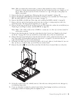
When you replace the system board, you must either update the server with the latest
firmware or restore the pre-existing firmware that the customer provides on a diskette or CD
image. Make sure that you have the latest firmware or a copy of the pre-existing firmware
before you proceed.
4.
Remove the riser-card assembly (see “Removing the riser-card assembly” on page 75).
5.
Remove the IBM ServeRAID-BR10il v2 SAS/SATA controller if one is installed (see “Removing an
IBM ServeRAID-BR10il v2 SAS/SATA Controller” on page 77).
6.
Remove the DIMM air baffle (see “Removing and installing the DIMM air baffle” on page 31).
7.
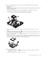
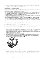
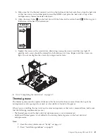
Remove the heat sink and microprocessor, and set them aside on a static-protective surface for
reinstallation (see “Removing the microprocessor” on page 58).
8.
Remove the memory modules and set them aside on a static-protective surface for reinstallation (see
“Replacing or installing a memory module (DIMM)” on page 32).
Note:
Make a note of the location of each DIMM as you remove it, so that you can later reinstall it
in the same connector.
9.
Remove the virtual media key from the system board and set it aside (see “Replacing the virtual
media key” on page 82). You must reinstall the virtual media key on the new system board.
10.
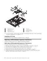
Remove the hypervisor flash device from the USB connector on the system board and set it aside
(see “Replacing a USB embedded hypervisor flash device” on page 52). You must reinstall the
hypervisor flash device on the new system board.
11.
Disconnect all cables from the system board. Make a list of each cable as you disconnect it; you can
then use this as a checklist when you install the new system board.
12.
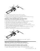
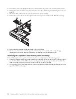
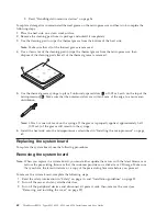
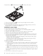
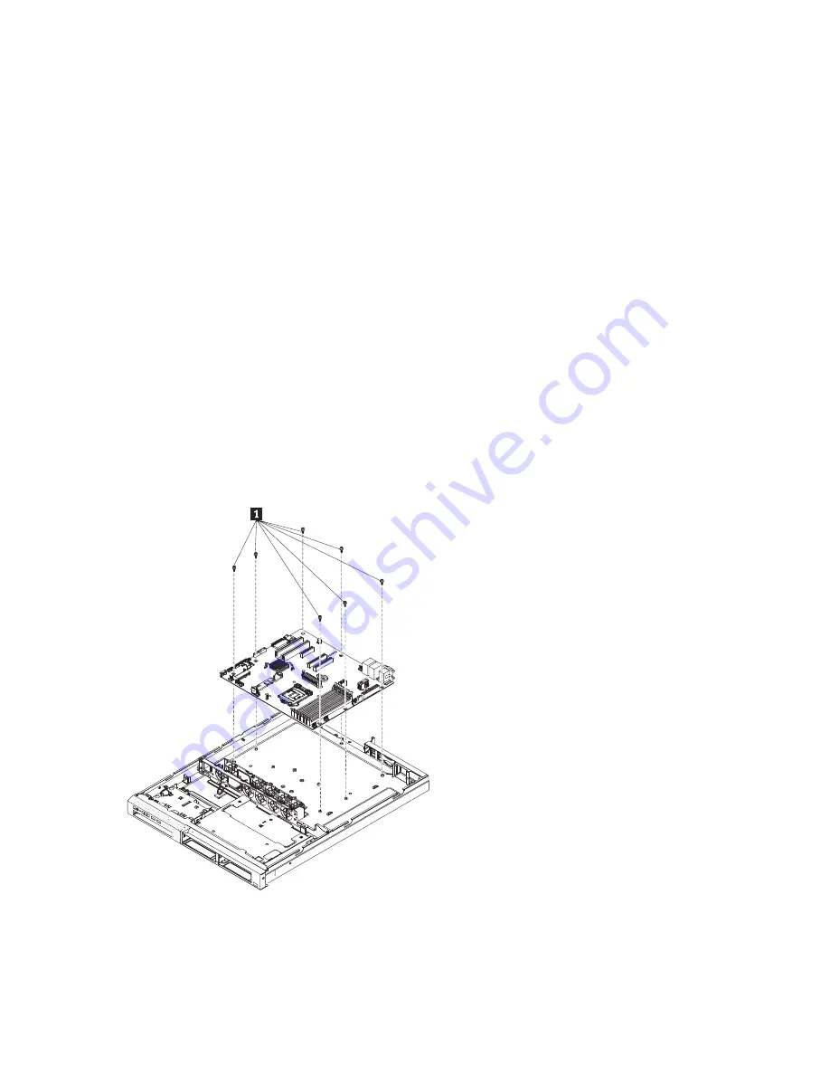
Remove the screws
1
that secure the system board to the chassis, and put them in a safe place.
13.
Lift up the system board and carefully remove it from the server, being careful not to damage any
surrounding components.
14.
If you are instructed to return the system board, follow all packaging instructions, and use any
packaging materials for shipping that are supplied to you.
Chapter 6. Replacing CRUs and FRUs
63
Содержание 653417U
Страница 1: ...Installation and User Guide ThinkServer RS210 Machine Types 6531 6532 6533 and 6534 ...
Страница 2: ......
Страница 3: ...ThinkServer RS210 Types 6531 6532 6533 and 6534 Installation and User Guide ...
Страница 8: ...vi ThinkServer RS210 Types 6531 6532 6533 and 6534 Installation and User Guide ...
Страница 16: ...xiv ThinkServer RS210 Types 6531 6532 6533 and 6534 Installation and User Guide ...
Страница 20: ...4 ThinkServer RS210 Types 6531 6532 6533 and 6534 Installation and User Guide ...
Страница 22: ...6 ThinkServer RS210 Types 6531 6532 6533 and 6534 Installation and User Guide ...
Страница 40: ...24 ThinkServer RS210 Types 6531 6532 6533 and 6534 Installation and User Guide ...
Страница 66: ...50 ThinkServer RS210 Types 6531 6532 6533 and 6534 Installation and User Guide ...
Страница 128: ...112 ThinkServer RS210 Types 6531 6532 6533 and 6534 Installation and User Guide ...
Страница 160: ...144 ThinkServer RS210 Types 6531 6532 6533 and 6534 Installation and User Guide ...
Страница 164: ...148 ThinkServer RS210 Types 6531 6532 6533 and 6534 Installation and User Guide ...
Страница 172: ...Taiwanese Class A warning statement 01 156 ThinkServer RS210 Types 6531 6532 6533 and 6534 Installation and User Guide ...
Страница 173: ...Chinese Class A warning statement Korean Class A warning statement Appendix B Notices 157 ...
Страница 174: ...158 ThinkServer RS210 Types 6531 6532 6533 and 6534 Installation and User Guide ...
Страница 179: ......
Страница 180: ...Printed in USA ...

