


crystal User Manual
Version: 6.6.0/2
351/459
19. Configuring Custom Logical Behaviour
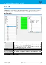
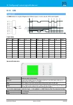
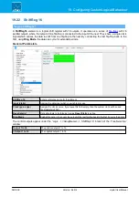
19.11
Gate
"Logic -> Gate"
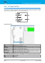
A
Gate
element is a logical GATE. It can be used to swap two groups of signals (A to B), where each group
has 8 inputs and 8 outputs. For example, to switch the output of a monitoring source selector between
Loudspeakers and Phones.
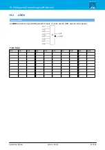
General Parameters
GATE
Reference name for the element.
Reverse A/B
Assigns the input control signal which will action the A to B switch.
When the input control signal is a logical “0” then
In A.1
to
In A.8
are routed to
Out A.1
to
Out
A.8
, and
In B.1
to
In B.8
are routed to
Out B.1
to
Out B.8
.
When the input control signal is a logical “1” then
In A.1
to
In A.8
are routed to
Out B.1
to
Out
B.8
, and
In B.1
to
In B.8
are routed to
Out A.1
to
Out A.
8.
In A.1 to A.8
Assign the 8 group A input signals.
In A.1 to A.8
Assign the 8 group B input signals.
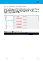
The control outputs appear under the “Logic -> <GroupName> -> Gate” branch of the 'Tree Selection' window:
Out A.1 to Out A.8
Group A outputs.
Out B.1 to Out B.8
Group B outputs.