johNSoN coNtroLS
2-48
ForM 102.20-N1 (1109)
installation
Water treatment
Any copper tube coils may be attacked by acid
condensate. The practice of boiler water treatment
should include CO
2
removal to assure longer tube
life.
Freeze Protection
Chilled water, hot water and steam coils can be
damaged during freezing weather. Precautionary
measures must be taken to prevent freezing such as:
•
Positive coil freeze protection must be used in
installations where any part of the water coil
is subjected to temperatures of 32°F or lower.
This may be accomplished by using a suitable
antifreeze solution. If the coil is not in use, it is
recommended that the coil be completely drained
and the inside of the tubes blown dry with com-
pressed air.
• After draining, flush coils with an antifreeze so
-
lution such as glycol. A solution of 50% glycol
and 50% water will protect from freezing to ap
-
proximately 35°F below zero at sea level.
Also,
refer to ASHRAE and ARI guidelines.
•
During winter operation due to the possibility of
shutdowns such as power failure, night shutdown
and weekend shutdown, the controls should be
installed so the return air dampers will go to the
full open position, and all fresh air dampers go
to the full closed position. A source of auxiliary
heat must be maintained inside the unit cabi-
net.
•
Other means of protection such as various
electro-mechanical switches and the full constant
flow of water can be used; however, Johnson
Controls will not be responsible for any coils
damaged by freezing.
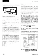
Steam
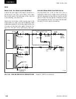
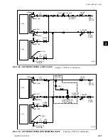
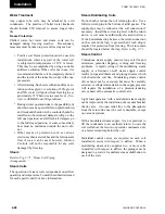
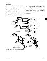
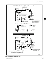
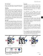
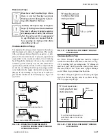
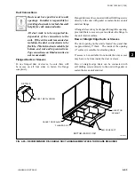
Refer to Fig. 2-71 “Steam Coil Piping
Arrangements.”
Steam Coils
The operation of steam coils is dependent on airflow
quantity and temperature. Consult the submittal issued
for each specific unit for above information.
Steam distributing Coils
Do not bush or reduce the coil return pipe size. Use a
full size return pipe to the bottom of a dirt pocket. The
supply pipe may be reduced at the coil connection if
necessary. Install the coil casing level with the return
down. A coil must be sufficiently elevated to allow a
12 inch minimum drop between the return connection
on the coil and the trap. A greater than 2 inch drop is
required for protection from freezing. The return main
should be located below the trap.
Refer to Fig. 2-71.
Steam Control
Continuous steam supply ensures long coil life and
minimizes potential trapping, venting and freezing
problems. A rapid cycling of the modulating steam
supply or a frequent on-off steam supply control
results in repeated thermal and piping stresses which
will shorten the coil life. Modulating steam control
valves must not be oversized but must be carefully
selected. A substantial variation in the supply pressure
will require the installation of a pressure-reducing
valve ahead of the automatic control valve.
Light load operation with a modulated steam supply
can be improved by the installation of a vacuum breaker
check valve. An open relief line to the atmosphere
from the return line near the coil is desirable, except
on vacuum systems.
With a modulated steam supply, it is not practical to
lift the condensate to an overhead return. Locate the
coil well above the return, or provide condensate unit,
or a boiler return trap below the coil.
Individual control valves are required on each coil
installed in series with respect to airflow. When a
modulating steam valve supplies two or more coils
in parallel, with respect to airflow, the piping must be
designed to provide for uniform steam distribution to
each of the coils.
Содержание YORK SOLUTION LD09624
Страница 4: ...johnson controls 4 FORM 102 20 N1 1109 THIS PAGE INTENTIONALLY LEFT BLANK ...
Страница 10: ...johnson controls 10 FORM 102 20 N1 1109 THIS PAGE INTENTIONALLY LEFT BLANK ...
Страница 16: ...johnson controls 16 FORM 102 20 N1 1109 THIS PAGE INTENTIONALLY LEFT BLANK ...
Страница 30: ...johnson controls 1 8 FORM 102 20 N1 1109 THIS PAGE INTENTIONALLY LEFT BLANK ...
Страница 106: ...johnson controls 2 76 FORM 102 20 N1 1109 THIS PAGE INTENTIONALLY LEFT BLANK ...
Страница 133: ...3 27 johnson controls FORM 102 20 N1 1109 3 FIG 3 28 AIR handler start up checklist FORM 100 00 CL1 ...


