johNSoN coNtroLS
2-18
ForM 102.20-N1 (1109)
installation
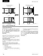
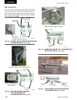
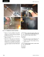
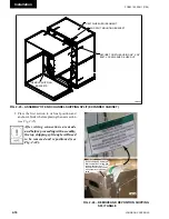
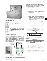
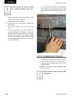
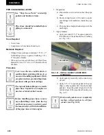
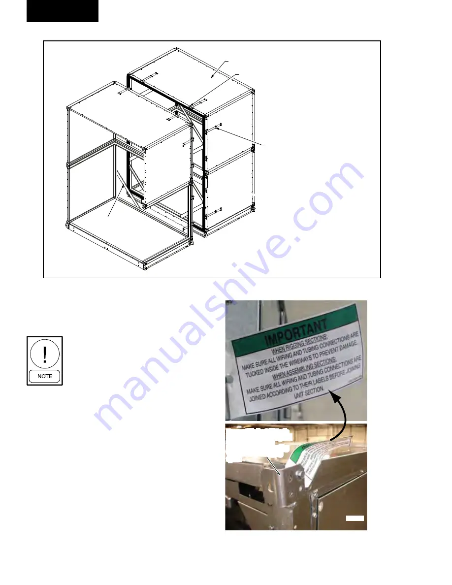
Fig. 2-24 – REMOVE And REPOSitiOn ShiPPing
SPlit AnglE
SECURE TOGETHER USING 3/8" X 3/4"
BOLT, LOCK WASHER & HEX NUT.
REMOVE SHIPPING
BRACKETS
HEAT WHEEL (ER) SEGMENT
END SPLIT MOUNTING BRACKET
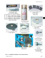
FIG. 2-23 – ASSEMBLY OF END CHANNEL SHIPPING SPLIT (EXPANDED CABINET)
LD14262
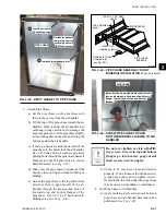
2. Place the first section in its final position and
anchor or block it before placing the next section
(
see Fig. 2-25).
After wiring connections are made
and before proceeding with assembly,
the top shipping split angle will need
to be removed and repositioned (see
Fig. 2-24).
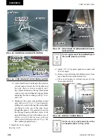
Remove Shipping Split Angle
after completion of wiring and
tubing placement and
reposition before proceeding
with assembly of shipping
splits.
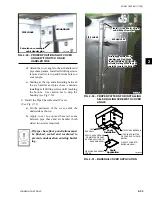
Remove Shipping Split Angle
after completion of wiring and
tubing placement and
reposition before proceeding
with assembly of shipping
splits.
LD14097
Содержание YORK SOLUTION LD09624
Страница 4: ...johnson controls 4 FORM 102 20 N1 1109 THIS PAGE INTENTIONALLY LEFT BLANK ...
Страница 10: ...johnson controls 10 FORM 102 20 N1 1109 THIS PAGE INTENTIONALLY LEFT BLANK ...
Страница 16: ...johnson controls 16 FORM 102 20 N1 1109 THIS PAGE INTENTIONALLY LEFT BLANK ...
Страница 30: ...johnson controls 1 8 FORM 102 20 N1 1109 THIS PAGE INTENTIONALLY LEFT BLANK ...
Страница 106: ...johnson controls 2 76 FORM 102 20 N1 1109 THIS PAGE INTENTIONALLY LEFT BLANK ...
Страница 133: ...3 27 johnson controls FORM 102 20 N1 1109 3 FIG 3 28 AIR handler start up checklist FORM 100 00 CL1 ...


