johNSoN coNtroLS
2-6
ForM 102.20-N1 (1109)
installation
Ceiling Suspended units
It is recommended that support is
structurally engineered to prevent
flexing, sagging or twisting of air
handlers.
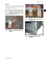
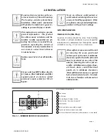
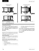
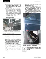
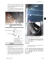
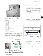
Refer to Fig. 2-6 “Ceiling Suspended Unit
”
for proper
support of unit in the direction of airflow and/or
perpendicular to the direction of airflow.
general Requirements
Johnson Controls recommends that ceiling suspension
of units be accomplished in the field with the
following:
Structure positioned perpendicular to airflow
The units must be supported (at a minimum) in the
following locations:
• Both ends.
• At each shipping split.
• Upstream and downstream of each cooling coil
segment.
• Under heavy components like fans, attenuators,
and heating segment.
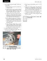
Do not obstruct door operation, filter
access, piping, electrical or control
connections with suspension mem-
bers.
Fig. 2-6 – CEiling SuSPEndEd unit
LD09619a
STRUCTURE PARALLEL TO AIRFLOW
(Units under 5 ft. wide)
(Units over 5 ft. wide)
STRUCTURE PERPENDICULAR TO AIRFLOW
FAN SECTION
ELEVATION VIEW
MC
RF
MB
FS
ELEVATION VIEW
CC
RF
MB
FAN SECTION
BDW COOLING
PLAN VIEW
AIR FLOW
FS
BDW COOLING
PLAN VIEW
AIR FLOW
Содержание YORK SOLUTION LD09624
Страница 4: ...johnson controls 4 FORM 102 20 N1 1109 THIS PAGE INTENTIONALLY LEFT BLANK ...
Страница 10: ...johnson controls 10 FORM 102 20 N1 1109 THIS PAGE INTENTIONALLY LEFT BLANK ...
Страница 16: ...johnson controls 16 FORM 102 20 N1 1109 THIS PAGE INTENTIONALLY LEFT BLANK ...
Страница 30: ...johnson controls 1 8 FORM 102 20 N1 1109 THIS PAGE INTENTIONALLY LEFT BLANK ...
Страница 106: ...johnson controls 2 76 FORM 102 20 N1 1109 THIS PAGE INTENTIONALLY LEFT BLANK ...
Страница 133: ...3 27 johnson controls FORM 102 20 N1 1109 3 FIG 3 28 AIR handler start up checklist FORM 100 00 CL1 ...

