3-3
johNSoN coNtroLS
ForM 102.20-N1 (1109)
3
PRE StARt uP FAn ASSEMBlY inSPECtiOn
When the unit is removed from long-
term storage moisture laden bearing
grease should be purged and replen-
ished with fresh grease per lubrication
decal. The motor should be meggered
to verify that the resistance is still at
a satisfactory level compared to the
value recorded prior to storage.
1. Check the bearings and locking collars
(refer to
Table 3-1, “Torque for Tightening Setscrews”).
tABlE 3-1 – tORQuE FOR tightEning
SEtSCREWS
SEtSCREW
diA.
HEX. SIZE
ACROSS
FlAtS
Min. RECOMMEndEd
tORQuE
inCh lBS.
FOOt lBS.
1/4
1/8
66 - 85
5.5 - 7.08
5/16
5/32
126 - 164
10.5 - 13.7
3/8
3/16
228 - 296
19.0 - 24.7
7/16
7/32
348 - 452
29.0 - 35.7
1/2
1/4
504 - 655
42.0 - 54.6
5/8
5/16
1104 - 1435
92.0 - 119.6
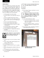
2. Verify fan wheel properly aligned, tight on shaft
and freely moving.
3. Ensure fan bearings properly lubricated (
see Fan
label or IOM Section 4, “Fan Bearing Lubrica-
tion
”).
4. Belts and Sheaves
a) Verify
sheaves properly aligned and tight on
shaft. Improper sheave alignment and belt
tension are potential causes of excessive noise
and vibration, as well as shortened belt and
bearing life (
see IOM Section 4, “Sheaves
Alignment
”).
b) Check belt tension. If not familiar with the
process
(see IOM Section 4, “Belts” and
“Adjustable Motor Base Operation”).
It is normal for belts to loosen after start up.
The new belts will “run in” or “take a set” by
seating slightly deeper into the grooves of the
sheaves. Recheck tension after one day and
three days.
c) Ensure motor mounting bolts and adjustable
motor base bolts are tight.
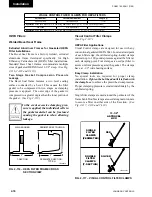
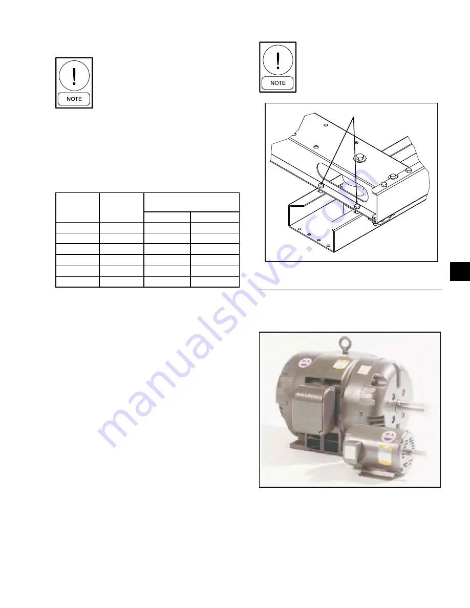
5. Verify tie down bolts removed from 4 corners of
fan base assembly.
In small units the tie down bolts may
only be applied to three corners of
the fan base since one corner is not
accessible.
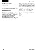
Motors - OdP vs. tEFC
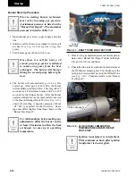
See Fig. 3-3 for ODP.
Fig. 3-2 – FAn And MOtOR iSOlAtOR SuPPORt
FRAME.
TIE DOWN BOLTS
LDO9638
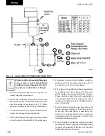
Fig. 3-3 – OdP (OPEn dRiP PROOF)
LD09635
Содержание YORK SOLUTION LD09624
Страница 4: ...johnson controls 4 FORM 102 20 N1 1109 THIS PAGE INTENTIONALLY LEFT BLANK ...
Страница 10: ...johnson controls 10 FORM 102 20 N1 1109 THIS PAGE INTENTIONALLY LEFT BLANK ...
Страница 16: ...johnson controls 16 FORM 102 20 N1 1109 THIS PAGE INTENTIONALLY LEFT BLANK ...
Страница 30: ...johnson controls 1 8 FORM 102 20 N1 1109 THIS PAGE INTENTIONALLY LEFT BLANK ...
Страница 106: ...johnson controls 2 76 FORM 102 20 N1 1109 THIS PAGE INTENTIONALLY LEFT BLANK ...
Страница 133: ...3 27 johnson controls FORM 102 20 N1 1109 3 FIG 3 28 AIR handler start up checklist FORM 100 00 CL1 ...

