johNSoN coNtroLS
2-38
ForM 102.20-N1 (1109)
installation
gas heat Option
Wiring of this device is the responsibility of the installer
if Single Point Power was not selected.
Panel locations and sizes vary based upon unit size and
burner configurations.
Burner voltage is selected to match primary unit
voltage.
Modulation control voltage to be 2-10 VDC as
standard.
Electrical penetrations can come through the floor
or side wall panels. Any penetration will have to
be drilled and must be properly sealed to keep out
moisture.
Refer to IOM Section 5
“
Field Penetrations
for Piping and Electrical Connections
”
.
Make power connections per wiring diagrams,
provided inside burner control panel. Also
see generic
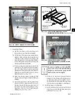
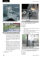
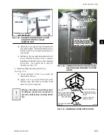
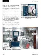
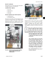
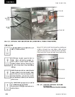
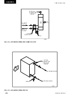
diagrams in IOM Section 6. Refer to Fig. 2-56 and
Fig. 2-57 for Gas Burner component locations.
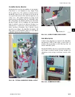
Terminal Strip for Power
and Controls.
Fig. 2-57 – MAin POWER And COntROl PAnEl
W/ COVER OPEn
LD11597
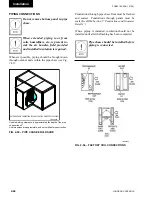
Fig. 2-56 – gAS BuRnER COMPOnEnt lOCAtiOnS
LD11596B
Inside of XTO Gas
Burner Pipe Chase.
Draft Damper
Adjustable Quadrant
Main Power and Control
Termination Panel w/ Gas
Burner ID and Ratings
Plate (see Fig 2-50 for
internal view).
Burner Control Panel
(contains Factory Test
Data Sheet,
Manufacturers IOM
and Burner Control
System.)
ID Fan
ID Fan Motor
Flue Connection
Safety Limits
plate (see Fig. 2-57 for
Содержание YORK SOLUTION LD09624
Страница 4: ...johnson controls 4 FORM 102 20 N1 1109 THIS PAGE INTENTIONALLY LEFT BLANK ...
Страница 10: ...johnson controls 10 FORM 102 20 N1 1109 THIS PAGE INTENTIONALLY LEFT BLANK ...
Страница 16: ...johnson controls 16 FORM 102 20 N1 1109 THIS PAGE INTENTIONALLY LEFT BLANK ...
Страница 30: ...johnson controls 1 8 FORM 102 20 N1 1109 THIS PAGE INTENTIONALLY LEFT BLANK ...
Страница 106: ...johnson controls 2 76 FORM 102 20 N1 1109 THIS PAGE INTENTIONALLY LEFT BLANK ...
Страница 133: ...3 27 johnson controls FORM 102 20 N1 1109 3 FIG 3 28 AIR handler start up checklist FORM 100 00 CL1 ...


