2-23
johNSoN coNtroLS
ForM 102.20-N1 (1109)
2
A
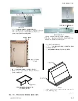
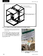
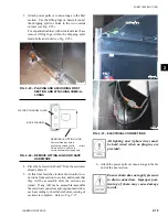
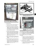
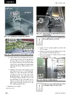
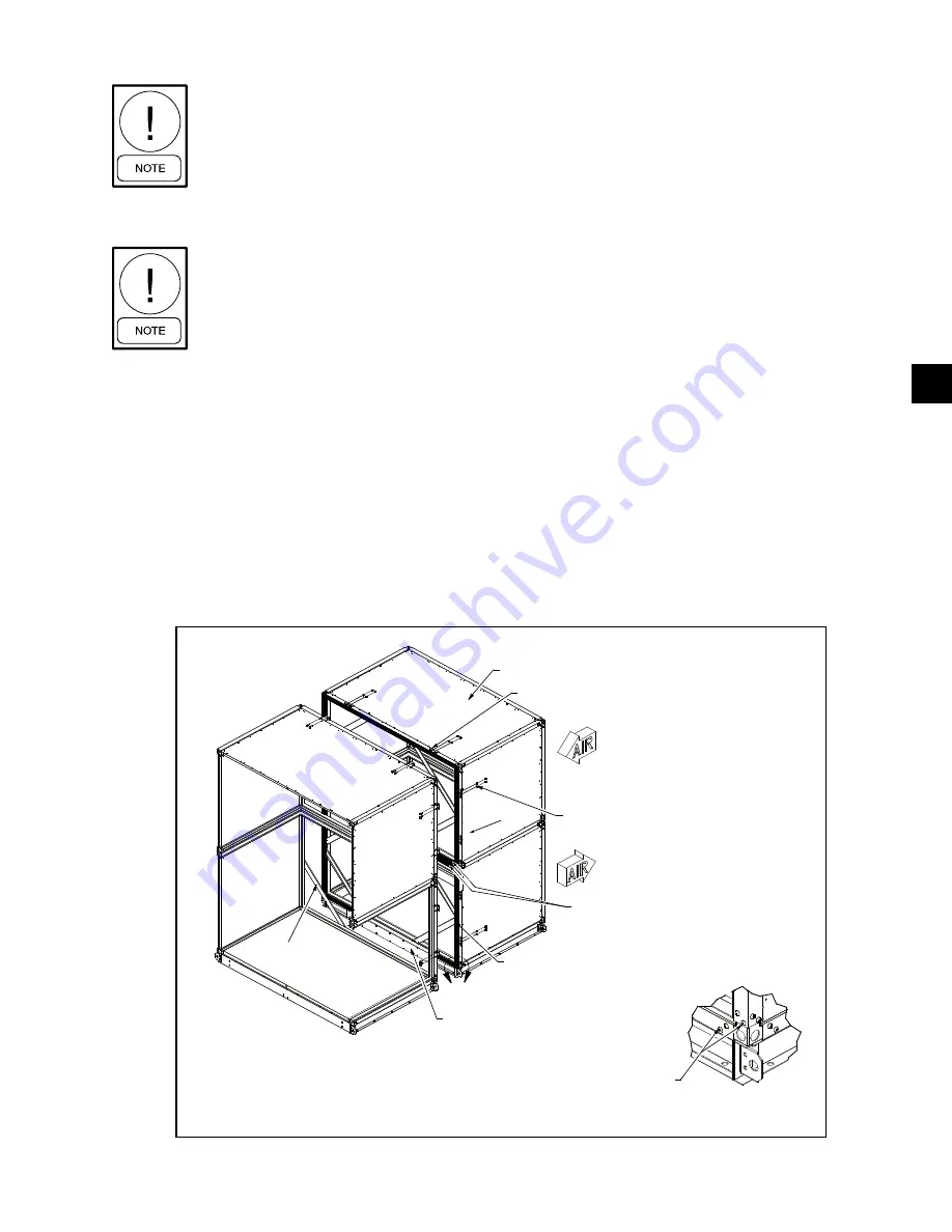
3/16" ALLEN HEAD SCREWS IN RACEWAY
CORNERS AT ENDS OF ALL SEGMENTS
JOINING TOGETHER; MUST BE REMOVED
PRIOR TO PULLING SECTIONS TOGETHER.
REMOVE BASERAIL SUPPORT PLATE
PRIOR TO SECURING LARGE UNITS
TOGETHER.
APPLY 1/4" x 2" NEOPRENE GASKET TO
ALL RACEWAY MATING SURFACES OF
ONE MATING SEGMENT.
SECURE TOGETHER USING 3/8" X 3/4"
BOLT, LOCK WASHER & HEX NUT.
REMOVE SHIPPING
BRACKETS
DETAIL A
HEAT WHEEL (ER) SEGMENT
END SPLIT MOUNTING BRACKET
INCLUDE 2 GASKETS SIDE BY
SIDE ON INTERMEDIATE
RACEWAY SURFACES.
Fig. 2-33 – ASSEMBlY OF End ChAnnEl ShiPPing SPlit
LD12357
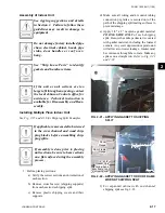
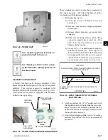
See “Ship loose Parts” to identify
gaskets and hardware items.
Assembly of End Channel Shipping Split
The assembly is the same regardless of
what sections are being connected to-
gether. The vertical Energy Recovery
Wheel shown in Fig. 2-33 is a common
example
Prior to pulling sections together:
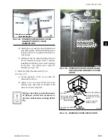
1. Remove baserail support plate (large units).
2. Remove shipping brackets in corners.
3. Remove screws in raceway corners at ends of all
segments joining together
(as shown in Detail A
of Fig. 2-33).
4. Clean the metal surface where gasket is to be
applied with mineral spirits or rubbing alcohol.
5. Apply 1/4" x 2" neoprene gasket to all raceway
mating surfaces of one mating section. Include
two gaskets side by side on intermediate raceway
surfaces (large units).
6. Ensure that the sections are not racked and will
line up properly.
Attach sections as follows:
1. Make sure assembly surface is clean and level
to allow the sections to slide freely. If surface
is irregular, use metal shims under sections as
necessary to align mating surfaces.
2. Pull sections together using a come along, draw
-
ing the base together.
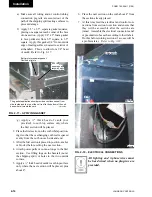
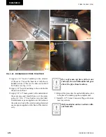
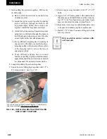
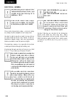
3. Attach the sides of the sections. Beginning at the
bottom of the sections secure the end channel as-
sembly brackets together using 3/8" x 3/4" Allen
head bolts, lock washers hex nuts at each bracket
. Continue securing the end channel assembly
brackets together, working from bottom to top,
pulling the sections tight.
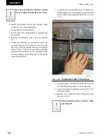
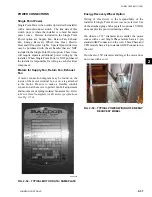
4. After the sides are secured, secure the brackets on
top of the unit with the same hardware mentioned
in step 3.
(EnERgY RECOVERY WhEEl ShOWn)
Содержание YORK SOLUTION LD09624
Страница 4: ...johnson controls 4 FORM 102 20 N1 1109 THIS PAGE INTENTIONALLY LEFT BLANK ...
Страница 10: ...johnson controls 10 FORM 102 20 N1 1109 THIS PAGE INTENTIONALLY LEFT BLANK ...
Страница 16: ...johnson controls 16 FORM 102 20 N1 1109 THIS PAGE INTENTIONALLY LEFT BLANK ...
Страница 30: ...johnson controls 1 8 FORM 102 20 N1 1109 THIS PAGE INTENTIONALLY LEFT BLANK ...
Страница 106: ...johnson controls 2 76 FORM 102 20 N1 1109 THIS PAGE INTENTIONALLY LEFT BLANK ...
Страница 133: ...3 27 johnson controls FORM 102 20 N1 1109 3 FIG 3 28 AIR handler start up checklist FORM 100 00 CL1 ...

