johNSoN coNtroLS
6
ForM 102.20-N1 (1109)
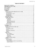
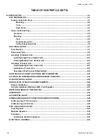
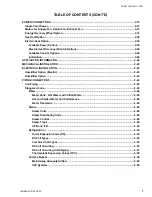
2.0 inStAllAtiOn ...........................................................................................................................................2-1
SitE PREPARAtiOn .................................................................................................................................2-1
Outdoor units (Site Prep) .....................................................................................................................2-1
Mounting ......................................................................................................................................2-2
Curb .............................................................................................................................................2-2
Steel Frame .................................................................................................................................2-3
indoor units (Site Prep) ........................................................................................................................2-3
Clearance ..........................................................................................................................................2-5
Mounting ...........................................................................................................................................2-5
Floor .............................................................................................................................................2-5
housekeeping Pad ......................................................................................................................2-5
Ceiling Suspended units ...........................................................................................................2-6
unit inStAllAtiOn .................................................................................................................................2-7
tools needed .........................................................................................................................................2-7
Ship loose Parts ...................................................................................................................................2-8
Assembly of Outdoor unit ..................................................................................................................2-13
installing Single Piece Outdoor unit ............................................................................................2-13
installing Multiple Piece Outdoor unit ........................................................................................2-13
Assembly of indoor unit .....................................................................................................................2-17
installing Multiple Piece indoor unit ...........................................................................................2-17
installation of tiered unit ..............................................................................................................2-21
Assembly of End Channel Shipping Split ...................................................................................2-23
hOOd inStAllAtiOn With OPtiOnAl MiSt EliMinAtORS ............................................................2-24
OutdOOR AiR tEMPERAtuRE And/OR huMiditY SEnSORS ........................................................2-24
ACtuAtOR inStAllAtiOn ...................................................................................................................2-25
inStAllAtiOn OF MultiZOnE (MZ) dAMPERS .................................................................................2-26
damper installation .............................................................................................................................2-26
Actuator installation Mutlizone (MZ) - Field Supplied .....................................................................2-27
inERtiA FAn BASE Fill inStRuCtiOn ..............................................................................................2-27
huMidiFiERS ...........................................................................................................................................2-27
uVC EMittER lightS ...........................................................................................................................2-28
AiR MEASuRing dEViCE COnnECtiOnS (WhEn PROVidEd) .........................................................2-29
Air Measuring at the Fan inlets .........................................................................................................2-29
Air Measuring at unit inlets ................................................................................................................2-29
PiPE ChASE inStAllAtiOn .................................................................................................................2-30
tools Required ....................................................................................................................................2-30
Materials Required ..............................................................................................................................2-30
Procedure ............................................................................................................................................2-30
Condensate drain Arrangement ...................................................................................................2-35
ElECtRiCAl - gEnERAl .......................................................................................................................2-36
tABlE OF COntEntS (COnt'd)
Содержание YORK SOLUTION LD09624
Страница 4: ...johnson controls 4 FORM 102 20 N1 1109 THIS PAGE INTENTIONALLY LEFT BLANK ...
Страница 10: ...johnson controls 10 FORM 102 20 N1 1109 THIS PAGE INTENTIONALLY LEFT BLANK ...
Страница 16: ...johnson controls 16 FORM 102 20 N1 1109 THIS PAGE INTENTIONALLY LEFT BLANK ...
Страница 30: ...johnson controls 1 8 FORM 102 20 N1 1109 THIS PAGE INTENTIONALLY LEFT BLANK ...
Страница 106: ...johnson controls 2 76 FORM 102 20 N1 1109 THIS PAGE INTENTIONALLY LEFT BLANK ...
Страница 133: ...3 27 johnson controls FORM 102 20 N1 1109 3 FIG 3 28 AIR handler start up checklist FORM 100 00 CL1 ...


