johNSoN coNtroLS
2-32
ForM 102.20-N1 (1109)
installation
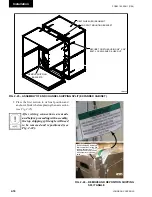
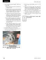
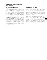
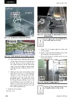
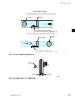
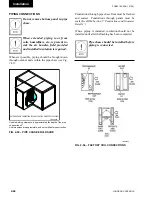
b) Add a small bead of caulking to the exterior
vertical seam between the air handler and
the pipe chase to insure complete seal.
Pay special attention to the top and bottom
corners, raceway and baserail engagements
and under the roof overhang (
see Fig.'s 2-45
and 2-47).
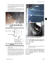
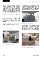
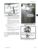
c) Starting at the center, and working toward
each end, run 1/4"-14 x 1" hex head self-
drilling screws down through the air handler
overhang into the top of the pipe chase
through the gasket. Use caution not to strip
the 20-gage housing with the screws. Line
up self-drilling screws with double row of
screws on top of unit raceway, plus one
spaced evenly between each
(see Fig. 2-46)
(No caulking required here.)
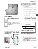
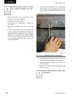
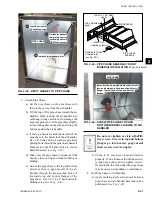
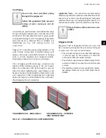
5. Install the Cover Angles
(See Fig. 2-48)
Cover angles must be installed before
the caulk from step 4 dries.
a) Apply 1/4" x 2" neoprene gasket to contact side
of cover angle.
b) Remove top and bottom self-drilling screws from
pipe chase and set aside for later use.
c) Place cover angles in vertical corners of pipe
chase and unit wall.
Notch on cover angle must be on the
air handler side (see Fig. 2-48).
AIR HANDLER
PIPE CHASE
Cover Angle
shown with
gasket side
out
AIR HANDLER
PIPE CHASE
Install Cover
Angle between
Air Handler and
Pipe Chase
before caulk
dries
Install Cover
Angle between
Air Handler and
Pipe Chase
before caulk
dries
Cover Angle
shown with
gasket side
out
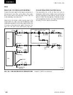
Fig. 2-48 – inStAll COVER AnglE
ld12564
Fig. 2-45 – BASERAil CAulK APPliCAtiOn
Caulk as shown by
dotted line (visible)
and
dashed line (hidden).
Caulk as shown by
dotted line (visible)
and
dashed line (hidden).
AIR HANDLER
AIR HANDLER
PIPE CHASE
PIPE CHASE
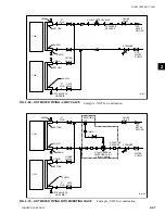
Fig. 2-46 – PiPE ChASE tO ROOF inStAllAtiOn
Install self-drilling
screws starting in
middle and working
towards ends.
Install self-drilling
screws starting in
middle and working
towards ends.
5
5
3
3
1
1
2
2
4
4
Line up self-drilling
screws with existing
screws on roof.
Line up self-drilling
screws with existing
screws on roof.
AIR HANDLER
AIR HANDLER
PIPE CHASE
PIPE CHASE
ld12035A
Apply caulk between
Pipe Chase and Air
Handler
Apply caulk between
Pipe Chase and Air
Handler
AIR HANDLER
AIR HANDLER
PIPE CHASE
PIPE CHASE
Fig. 2-47 – PiPE ChASE tO AiR hAndlER CAulK
APPliCAtiOn
ld12565
Содержание YORK SOLUTION LD09624
Страница 4: ...johnson controls 4 FORM 102 20 N1 1109 THIS PAGE INTENTIONALLY LEFT BLANK ...
Страница 10: ...johnson controls 10 FORM 102 20 N1 1109 THIS PAGE INTENTIONALLY LEFT BLANK ...
Страница 16: ...johnson controls 16 FORM 102 20 N1 1109 THIS PAGE INTENTIONALLY LEFT BLANK ...
Страница 30: ...johnson controls 1 8 FORM 102 20 N1 1109 THIS PAGE INTENTIONALLY LEFT BLANK ...
Страница 106: ...johnson controls 2 76 FORM 102 20 N1 1109 THIS PAGE INTENTIONALLY LEFT BLANK ...
Страница 133: ...3 27 johnson controls FORM 102 20 N1 1109 3 FIG 3 28 AIR handler start up checklist FORM 100 00 CL1 ...

