johNSoN coNtroLS
2-62
ForM 102.20-N1 (1109)
installation
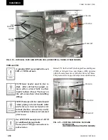
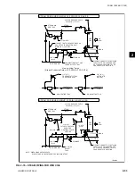
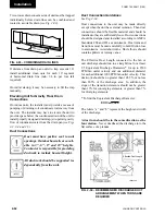
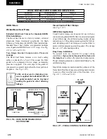
Two or more drains on same side of unit must be trapped
individually before drain lines can be combined and
routed to a suitable drain (
see Fig. 2-93
).
If distance from drain pan outlet to trap exceeds 10',
install additional clean outs for each 10' segment
of horizontal drain line (min. 1/4 in. per foot fall
required).
On initial startup, it may be necessary to fill the trap
manually.
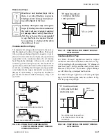
Elevating unit for gravity Floor drain
Connections
On indoor units, the installer must provide a means of
pumping or draining coil condensate water away from
the unit. The installer may have to elevate the unit to
provide space below the condensate drain of the unit to
install properly designed drain trap(s) to permit gravity
flow of condensate water from the drain pan (
see Figs
2-3, 2-4 and 2-5
).
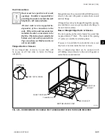
duct Connections
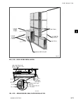
Duct must have positive seal to unit
openings. Outdoor baserails are avail-
able in 3", 6", 8" and 10" heights.
Contractor is responsible for providing
ductwork to include baserail height.
All ductwork should be supported in-
dependently from the unit.
LD06345-1
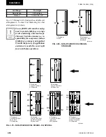
Fig. 2-93 – COMBining dRAin linES
TRAPS
Duct Connection Guidelines
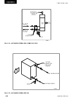
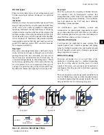
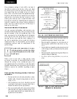
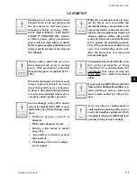
See Fig. 2-94.
Duct connections to the unit may be made directly
except when the unit has external isolation. Then duct
connections should be flexible material and should be
installed so they are sufficiently loose. Duct connections
should be designed and installed according to AMCA
Standards 200 and 201 as a minimum. Duct turns and
transitions must be made carefully to hold friction loss
to a minimum. Avoid short turns. Duct elbows should
contain splitters or turning vanes.
The Effective Duct Length connected to the fan or
unit discharge should run in a straight line for at least
2.5 Equivalent Discharge Diameters* for up to 2500
FPM fan outlet velocity and one additional diameter
for each additional 1000 FPM fan outlet velocity. This
ductwork should be no greater than 105.5% or no less
than 85.5% of the discharge area. In addition, the
slope of the transition elements should not be greater
than 15% for converging elements, or greater than 7%
for diverging elements.
* To find the Equivalent Discharge Diameter:
The letters “a” and “b” represent the height and width
of the discharge.
A duct turn should be in the same direction as the
fan rotation.
Never deadhead the discharge into the
flat surface of a plenum.
edd = 4ab/�
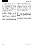
Fig. 2-94 – RECOMMEndEd diSChARgE duCt
ARRAngEMEnt WhEn tuRnS ARE
REQuiREd
Effective Duct Length
LD06335-2
Содержание YORK SOLUTION LD09624
Страница 4: ...johnson controls 4 FORM 102 20 N1 1109 THIS PAGE INTENTIONALLY LEFT BLANK ...
Страница 10: ...johnson controls 10 FORM 102 20 N1 1109 THIS PAGE INTENTIONALLY LEFT BLANK ...
Страница 16: ...johnson controls 16 FORM 102 20 N1 1109 THIS PAGE INTENTIONALLY LEFT BLANK ...
Страница 30: ...johnson controls 1 8 FORM 102 20 N1 1109 THIS PAGE INTENTIONALLY LEFT BLANK ...
Страница 106: ...johnson controls 2 76 FORM 102 20 N1 1109 THIS PAGE INTENTIONALLY LEFT BLANK ...
Страница 133: ...3 27 johnson controls FORM 102 20 N1 1109 3 FIG 3 28 AIR handler start up checklist FORM 100 00 CL1 ...

