johNSoN coNtroLS
2-36
ForM 102.20-N1 (1109)
installation
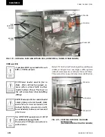
DO NOT PENETRATE any main or
auxiliary drain pan.
DO NOT PENETRATE roof of out-
door unit.
DO NOT PENETRATE WIREWAyS
in any manner. These sheet metal
channels, which run along the top
panel, contain electrical wires and
connections. Electrical shock and/or
damage to the unit may result.
Electrical drawings are provided in the information
packet on the inside of a unit access door. Major
optional components will have specific electrical and
IOM information packed inside their control panels
or attached.
See IOM Section 6 for generic electrical
drawings.
ElECtRiCAl - gEnERAl
All field wiring must conform to the
National Electrical Code (N.E.C.) and
possible local codes that may be in
addition to N.E.C.
Unit is E.T.l. listed. Some compo-
nents are U.l. labeled. Any changes
in the field may affect their validity.
The current characteristics, phase, cycle and voltage
are stamped on the nameplate of each component.
Electrical conduit connections made to exposed boxes
on units should be made on the bottom of the box.
Installation should comply with code requirements.
Outdoor installation must be made watertight.
The installing contractor is responsible for electrical
conduit penetrations through the building roof.
Penetrations through panels must be sealed
(see IOM
Section 5 “Penetrations and Grommet Details
”
).
Electrical conduits that penetrate the
exterior (walls, pipe chase or floors)
of the unit will need to be externally
and internally sealed so that uncon-
ditioned air will not be drawn into
the unit through and around conduit.
This unconditioned air will result in
condensation that will fail components
prematurely.
All accessible electrical connections
must be checked for tightness prior to
the actual startup. Many of the con-
nections contain several strands of
wire, and while they were tightened at
the time of assembly, they should be
checked and re-tightened if needed.
The danger of a poor connection is
overheating and component failure.
Содержание YORK SOLUTION LD09624
Страница 4: ...johnson controls 4 FORM 102 20 N1 1109 THIS PAGE INTENTIONALLY LEFT BLANK ...
Страница 10: ...johnson controls 10 FORM 102 20 N1 1109 THIS PAGE INTENTIONALLY LEFT BLANK ...
Страница 16: ...johnson controls 16 FORM 102 20 N1 1109 THIS PAGE INTENTIONALLY LEFT BLANK ...
Страница 30: ...johnson controls 1 8 FORM 102 20 N1 1109 THIS PAGE INTENTIONALLY LEFT BLANK ...
Страница 106: ...johnson controls 2 76 FORM 102 20 N1 1109 THIS PAGE INTENTIONALLY LEFT BLANK ...
Страница 133: ...3 27 johnson controls FORM 102 20 N1 1109 3 FIG 3 28 AIR handler start up checklist FORM 100 00 CL1 ...

