P/N 14000A-PRERAD
ES50LVP / ES90LVP
PREMIUM MODULATING
AIR HANDLER
Installation, Operation and Maintenance Manual
RADIANT 101 Sharer Road Woodbridge, ON L4L 8Z3 Tel: 905-265-1527 Fax: 905-265-9739
Страница 1: ...P N 14000A PRERAD ES50LVP ES90LVP PREMIUM MODULATING AIR HANDLER Installation Operation and Maintenance Manual RADIANT 101 Sharer Road Woodbridge ON L4L 8Z3 Tel 905 265 1527 Fax 905 265 9739 ...
Страница 2: ...11 Rear Piping Connections 11 Ecosmart Mounting 12 Plumbing 12 Pump 13 PIPING DIAGRAMS 15 Typical Tankless Water Heater Piping 15 Typical Boiler Piping 16 ELECTRICAL 17 Electrical Information 17 Thermostat Wiring 17 Ecosmart ES50LVP ES90LVP Wiring Diagram 18 Miscellaneous Wiring 19 DIP SWITCH OPTIONS 20 Switch Locations 20 Outdoor Temperature Select 20 Heat CFM ES90LVP 21 Heat CFM ES50LVP 21 Syste...
Страница 3: ...E AND MAINTENANCE 26 Filter 26 Coils 26 Fan and Motor 26 Control and Blower Assembly Removal 26 TROUBLESHOOTING 27 Thermostat call error 27 External pump does not run 27 External pump is noisy at start up 27 Water heater temperature and pressure relief valve is weeping 27 Insufficient or no heat 27 Cold water at hot faucet 28 Fan runs for cooling but not for heating 28 Heating during standby mode ...
Страница 4: ... damage WARNING Improper installation may create a condition where the operation of the product could cause personal injury or property damage Only a qualified contractor installer or service agency should install this product Improper installation adjustment alteration service or maintenance can cause injury or property damage Refer to this manual for assistance CAUTION This product must be insta...
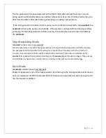
Страница 5: ...r to adjust for a wide variety of installations Various parameters are automatically monitored and fan and pump speeds vary simultaneously The ecosmart has a built in variable speed pump controller that can vary the speed of a standard single speed AC pump MODES OF OPERATION Three modes of operation are available 1 Full modulation full control of fan and pump requires outdoor temperature sensor 2 ...
Страница 6: ... outdoor sensor not installed Water temperature is set at the heat generator by referring to the heat generator performance data Fan operates at 50 of the HEAT CFM setting for 5 minutes then increases to 75 for a further 5 minutes then increases to 100 until the thermostat is satisfied If the pump is controlled by the ecosmart its speed will be adjusted accordingly as the ecosmart goes through its...
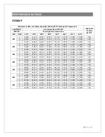
Страница 7: ...40 4 38 4 16 050 20 100 24 170 28 250 32 330 36 420 40 520 44 620 4 83 5 16 470 20 630 24 790 28 970 33 150 37 340 41 530 45 720 7 23 600 3 17 280 21 660 26 070 30 490 34 920 39 360 43 810 48 260 4 38 4 18 190 22 800 27 420 32 050 36 700 41 350 46 010 50 670 4 83 5 18 770 23 510 28 270 33 040 37 810 42 600 47 390 52 180 7 23 700 3 18 950 23 780 28 620 33 480 38 360 43 250 48 140 53 040 4 38 4 20 1...
Страница 8: ...680 63 050 69 420 6 27 900 3 24 040 30 150 36 290 42 450 48 610 54 790 60 980 67 180 4 05 4 25 850 32 400 38 980 45 570 52 180 58 800 65 420 72 050 4 19 5 27 010 33 850 40 710 47 580 54 460 61 360 68 260 75 160 6 27 1 000 3 25 430 31 900 38 400 44 920 51 460 58 000 64 560 71 130 4 05 4 27 530 34 520 41 530 48 560 55 610 62 670 69 740 76 810 4 19 5 28 900 36 220 43 560 50 920 58 300 65 690 73 080 8...
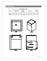
Страница 9: ...DATA INCHES Model Overall Dimensions W x D x H Supply Opening W x D Side Return Piping Location A B C D E F G H I J K ES50LVS 14 0 21 0 29 0 11 8 17 8 18 3 14 3 1 4 2 0 2 8 2 4 ES90LVS 21 0 21 0 29 0 18 8 17 8 18 3 14 3 1 4 2 0 2 8 2 4 ...
Страница 10: ...x 30 5 ES50LVP ECM blower performance amps CFM 0 1 WC 0 2 WC 0 3 WC 0 4 WC 0 5 WC 300 0 30 0 46 0 69 0 82 1 04 400 0 54 0 65 0 82 0 85 1 13 500 0 66 0 77 0 95 1 20 1 41 600 0 90 0 92 1 29 1 49 1 67 700 1 01 1 35 1 44 1 77 2 02 800 1 55 1 59 1 76 2 11 2 45 900 1 86 1 88 2 12 2 40 2 80 ES90LVP ECM blower performance amps CFM 0 1 WC 0 2 WC 0 3 WC 0 4 WC 0 5 WC 600 0 94 0 99 1 26 1 58 1 95 700 1 22 1 ...
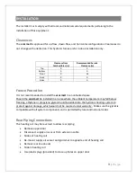
Страница 11: ...rt the hot water generating equipment per the manufacturer s recommendations Set the design water temperature to deliver the necessary amount of BTUs to the air handler 5 Once all air has been purged turn on the power to the ecosmart and set the room thermostat to heat and set the temperature high enough to initiate a call for heat This will energize the air handler an in turn the fan and pump 6 O...
Страница 12: ...n unheated space Should the ecosmart be installed in an area where the ambient temperature may fall below freezing ethylene or propylene glycol should be added into the hydronic heating system to protect against damage which would not be covered under warranty Make sure the glycol is compatible with all system components and is permitted by local and national codes Rear Piping Connections The heat...
Страница 13: ...the cabinet or from the bottom of the cabinet Position a filter rack so that the filter is readily accessible A filter and filter rack are not included Sides are marked for a standard 16 x 20 in filter rack WARNING Special care should be taken in the vicinity of the coil to avoid puncture Screw into opening flange instead of top of cabinet when fastening the supply air duct Plumbing Install a sedi...
Страница 14: ...ed for your system to meet local codes and to work effectively A check valve Protects against back flow of water to avoid short circuiting around the water heater during domestic use Protects against thermal siphoning Is required in all potable water systems Pump A pump is not included inside the ecosmart Whether you are using an external pump or an internal built in pump it should be sized for th...
Страница 15: ... the equipment has been refilled and all air is purged from the system before turning on the heater WARNING When the system requires water temperatures higher than 120F a mixing valve shall be installed to reduce domestic hot water temperature to safeguard against scalding Combo Systems The ecosmart is ideal for use in combo systems which provide space heating and domestic hot water from a single ...
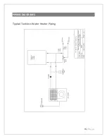
Страница 16: ...15 P a g e PIPING DIAGRAMS Typical Tankless Water Heater Piping ...
Страница 17: ...16 P a g e Typical Boiler Piping ...
Страница 18: ...ront panel Ratings data is located on the lower front panel The ecosmart operates on 120VAC 60Hz single phase line voltage All control circuits are standard 24VAC ecosmart must be grounded via the green wire within the control box Thermostat Wiring Any standard heat cool thermostat is compatible with the ecosmart Wire thermostat to lower right tabs as marked The ecosmart supports optional 2 stage ...
Страница 19: ...18 P a g e Ecosmart ES50LVP ES90LVP Wiring Diagram ...
Страница 20: ...h If there is a call for DHW fan will shut down and resume once the call for DHW has ended BOILER dry contacts to initiate heat source AUX 24V 24VAC output for humidifier or other accessory Active when heating is on OUTDOOR included outdoor temperature sensor connects here If sensor is not connected ecosmart assumes coldest temperature is present ...
Страница 21: ...w OUTDOOR TEMP set the lowest outdoor temperature expected HEAT CFM set 1 of 8 fan CFM rates for heating SYSTEM set various system parameters COOL CFM set 1 of 8 fan CFM rates for cooling Outdoor Temperature Select Select lowest possible expected outdoor temperature DESIGN TEMP C DESIGN TEMP F SWITCH 1 SWITCH 2 SWITCH 3 18 0 OFF OFF OFF 17 to 10 1 14 ON OFF OFF 9 to 0 15 32 OFF ON OFF 1 to 10 33 5...
Страница 22: ...WITCH 1 SWITCH 2 SWITCH 3 300 OFF OFF OFF 400 ON OFF OFF 500 OFF ON OFF 600 ON ON OFF 700 OFF OFF ON 800 ON OFF ON 900 OFF ON ON System ES990LVP and ES50LVP Select required system parameters Mode SWITCH 1 SWITCH 2 SWITCH 3 SWITCH 4 Full Modulation OFF OFF X X Step Modulation ON OFF X X Single Stage OFF ON X X Test Mode 1 ON ON X X Normal Fan Cooling 2 X X OFF X Dehumidification Fan Cooling 2 X X O...
Страница 23: ... for 15 min and then reverts back to rate set by COOL CFM 3 Normal Continuous Fan runs at rate set by HEAT CFM switch Low speed Continuous Fan runs at 50 of rate set by HEAT CFM switch Cool CFM ES90LVP CFM 0 5 WC SWITCH 1 SWITCH 2 SWITCH 3 600 OFF OFF OFF 700 ON OFF OFF 800 OFF ON OFF 900 ON ON OFF 1000 OFF OFF ON 1100 ON OFF ON 1200 OFF ON ON 1300 ON ON ON Cool CFM ES50LVP CFM 0 5 WC SWITCH 1 SWI...
Страница 24: ...ed R is disconnected from W Heat generator is turned off Auxiliary 24VAC power is turned off Pump turns off and fan speed ramps down to zero extracting any remaining heat in the coil Step Modulation Heating Mode ecosmart outdoor sensor not installed Thermostat calls for heat R is connected to W Heat generator is turned on Auxiliary 24VAC power is turned on Pump turns on 100 After a 15 second delay...
Страница 25: ... on Pump turns on at 100 After a 15 second delay to allow for system water to heat up coil fan ramps up to HEAT CFM speed Thermostat is satisfied R is disconnected from W Heat generator is turned off Auxiliary 24VAC power is turned off Pump turns off and fan speed ramps down to zero extracting any remaining heat in the coil Cooling Mode Modulation Step and Basic ecosmart outdoor sensor not install...
Страница 26: ...ate If SYSTEM switch 4 is ON fan runs at 50 of selected HEAT CFM rate If fan is set to OFF on thermostat fan runs at HEAT or COOL CFM settings Constant Low Fan Circulation Fan may be run at a low rate using system switch 4 as follows OFF fan runs at rate set by HEAT CFM switch ON fan runs at 50 of rate set by HEAT CFM switch Pump Exerciser The circulating pump is exercised for 1 min every 24 hr wh...
Страница 27: ...face of the heating coil Fan and Motor Check fan for dust once a year If dirty vacuum or wash to remove dust Keeping the fan blades clean will reduce noise and improve capacity and efficiency of the heating system Control and Blower Assembly Removal 1 Turn off main power 2 Disconnect power thermostat and any other miscellaneous wiring from the control board and remove them from the control casing ...
Страница 28: ...nd may need re purging If the heat source is a water heater check to make sure branch connections for the heating loop are horizontal to prevent the collecting of air in the loop Water heater temperature and pressure relief valve is weeping A check valve or back flow preventer may have been installed in the system Some form of pressure relief may be required Consult water heater manufacturer s ins...
Страница 29: ...eck valve repair or replace valve Fan runs for cooling but not for heating The room thermostat may be connected improperly Refer to Electrical section or wiring schematic on ecosmart for proper installation Heating during standby mode Probable cause is thermal siphoning WARRANTY Warranty is 2 years parts Visit ecosmartair com warranty htm for full details ...