2-39
johNSoN coNtroLS
ForM 102.20-N1 (1109)
2
Hook up power
(see Fig. 2-59 for power terminals
and Fig. 2-58 for control panel component location).
Terminals shown are for a 2 stage 24 VAC control
interface. Terminals may also require 120VAC
control interface based upon options selected.
See
wiring diagram on inside cover of electric heat control
panel.
Electrical conduits that penetrate the
exterior (walls, pipe chase or floors)
of the unit will need to be externally
and internally sealed so that uncon-
ditioned air will not be drawn into
the unit through and around conduit.
This unconditioned air will result in
condensation that will fail components
prematurely.
All accessible electrical connections
must be checked for tightness prior to
the actual startup. Many of the con-
nections contain several strands of
wire, and while they were tightened at
the time of assembly, they should be
checked and re-tightened if needed.
The danger of a poor connection is
overheating and component failure.
DO NOT PENETRATE any main or
auxiliary drain pan.
Electric heat Option
Wiring of this device is the responsibility of the installer
if Single Point Power was not selected.
Available Power Options
• 460V-3PH.
• 208/230V-3PH.
• 380V-3PH.
• 575V-3PH.
Electric Heat Disconnect Switch Options
• Fused Disconnect.
• Non-fused Disconnect.
Knockouts are provided on the top and bottom of the
enclosure for field penetrations. The YORK Solution
foam panel will have to be drilled to utilize these
knockout locations.
Refer to IOM Section 5 “Field
Penetrations for Piping and Electrical Connections
”
.
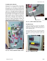
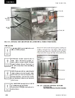
Control
Voltage
Transformer
Staging
Contactors
Main Disconnect
Switch & Field
Power Connections
(see Fig. 2-52).
Airflow
Proving
Switch
High
Temperature
Cutout
Knockouts
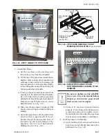
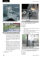
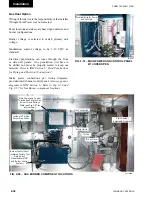
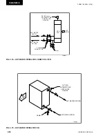
Fig. 2-58 – tYPiCAl ElECtRiC hEAt COntROl
PAnEl intERiOR WiRing And
COMPOnEntS
LD11594a
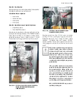
(see Fig. 2-59)
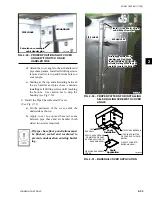
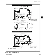
Fig. 2-59 – tYPiCAl FiEld COntROl And
POWER COnnECtiOnS
LD11595
Main Disconnect Switch
& Field Power Connections
Field Control Wiring
Interface Terminals
LD11595
Содержание YORK SOLUTION LD09624
Страница 4: ...johnson controls 4 FORM 102 20 N1 1109 THIS PAGE INTENTIONALLY LEFT BLANK ...
Страница 10: ...johnson controls 10 FORM 102 20 N1 1109 THIS PAGE INTENTIONALLY LEFT BLANK ...
Страница 16: ...johnson controls 16 FORM 102 20 N1 1109 THIS PAGE INTENTIONALLY LEFT BLANK ...
Страница 30: ...johnson controls 1 8 FORM 102 20 N1 1109 THIS PAGE INTENTIONALLY LEFT BLANK ...
Страница 106: ...johnson controls 2 76 FORM 102 20 N1 1109 THIS PAGE INTENTIONALLY LEFT BLANK ...
Страница 133: ...3 27 johnson controls FORM 102 20 N1 1109 3 FIG 3 28 AIR handler start up checklist FORM 100 00 CL1 ...


