johNSoN coNtroLS
3-12
ForM 102.20-N1 (1109)
Startup
Air Handler Pre Start Checks
•
Verify air handler has had proper start up and
airflow is at design maximum for heating cycle
(refer to air balance report).
•
Set bypass damper if provided in air handler.
•
Airflow proving switch for main supply fan in
-
stalled and operational.
• Check with Control Technician: two-minute
post-purge programmed in air handler controller.
Upon call for air handler unit stop, burner cycles
off then air handler fan cycles off two minutes
later.
Burner Pre Start Checks
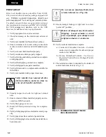
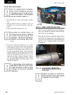
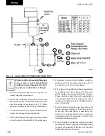
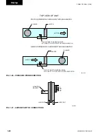
1. Open fuse disconnects before working on burner
(see Fig. 3-14).
Fig. 3-14 – OPEn FuSE diSCOnnECtS
2. Check all wire terminations for tightness.
3.
Check that the incoming voltage(s) are correct.
Compare measured voltages to burner motor and
ID motor nameplates and the “Burner Test Report”.
Reset fuse disconnects.
4. Check for correct rotation of 3 phase burner motor
and ID motor.
5. Verify that contractor has purged new gas lines of
air up to manual valve on gas train.
6. Valves which have been closed for shipping must
be opened accordingly. Check that all manual
valves operate without leaks.
ld12903
open fuse disconnects be-
fore working on burner.
BUrNer coNtroL
panel
7800
Series
relay
Preliminary Coordination
Contact contractor/customer who requested start-up.
• Verify air handler has had proper start-up.
• Ensure air handler and system is capable of de
-
sign airflow for gas heat start-up.
• Ensure reliable power is available.
• Verify gas lines are purged of air to equipment
valve.
• Verify controls are complete.
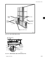
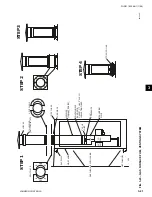
• Verify flue (stack) is correctly installed if parts
were shipped loose
(see Fig's 3-22 and 3-23).
Tools Recommended
•
Electrical Multimeter w/ Amprobe
•
Heating Unit Installation and Operation In-
struction
. - One is provided with every heating
unit for technical information and troubleshoot-
ing.
•
Magnehelic Gauge 0” To .25” WC, Dwyer Se-
ries 2000 or Model 1227 Dual Range Manom-
eter.
- For checking pressure over fire (draft).
•
Control Signal Generator, 0 to 20 mA (Al-
tek-234 or 334A)
- For 2 to 10 VDC signal add
500 ohms in series with signal generator.
•
Magnehelic Gauge 0” to 15” WC and 0 to 3 lbs.
(Dwyer series-2000) or Monometer (Dwyer-
1227) Duel Range Monometer
. - For checking
supply gas pressure and manifold gas pressure
or pilot gas pressure.
•
Honeywell - S7800A Test Module
- For use
on (Honeywell-7800) Series Relay Module.
(Available through Airside Parts - 800-545-7814,
Ext.12).
•
Flue Gas Analyzer (CO
2
and O
2
)
•
Stack Thermometer (0°F - 1000°F approx.)
•
Digital Manometer (replaces Magnehelic
Gauge).
Digital Manometer
Cat. #475-1 FM-AV
Series: 475-1 Mark III
Range: 0 to 19.99 In. W.C.
Dwyer Instruments, Inc.
Содержание YORK SOLUTION LD09624
Страница 4: ...johnson controls 4 FORM 102 20 N1 1109 THIS PAGE INTENTIONALLY LEFT BLANK ...
Страница 10: ...johnson controls 10 FORM 102 20 N1 1109 THIS PAGE INTENTIONALLY LEFT BLANK ...
Страница 16: ...johnson controls 16 FORM 102 20 N1 1109 THIS PAGE INTENTIONALLY LEFT BLANK ...
Страница 30: ...johnson controls 1 8 FORM 102 20 N1 1109 THIS PAGE INTENTIONALLY LEFT BLANK ...
Страница 106: ...johnson controls 2 76 FORM 102 20 N1 1109 THIS PAGE INTENTIONALLY LEFT BLANK ...
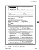
Страница 133: ...3 27 johnson controls FORM 102 20 N1 1109 3 FIG 3 28 AIR handler start up checklist FORM 100 00 CL1 ...

