MNP37M03GBV00 Date: 24-11 Rev. 0
Page 21 of 79
1
2
3
4
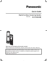
figure 5.04.5
1.
Assembly attachment piston
2.
Coffee dispensing nozzle
3.
Rotating arm nozzle
4.
Brass nut connecting the
Teflon tube to the assembly
After removing the assembly, place under running water to ensure it is completely
clean, particularly the areas where the brewing chamber metal filters and the grounds
puck discarding areas.
Dry the assembly meticulously with a cloth and install in place, following the above
steps in reverse order.
F
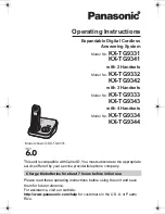
Important: to place the brewing assembly in operating position, the
assembly plate must coincide with the arrow on the plastic cover (no. 1 in fig.
5.04.6) and the motor cam that moves the assembly must be in standby
position, that is, pressing on the lower micro-switch (no. 2 in fig. 5.04.6)
1
2
figure 5.04.6
1.
Position for replacing coffee
assembly
2.
Position of motor cam
Содержание COFFEEMAR G-500 V2
Страница 1: ...MNP37M03GBV00 Date 24 11 Rev 0 Page 1 of 79 INGL S COFFEEMAR G 500 V2 USER S MANUAL...
Страница 26: ...MNP37M03GBV00 Date 24 11 Rev 0 Page 26 of 79 6 3 Electrical drawings Cabinet electrical drawing...
Страница 27: ...MNP37M03GBV00 Date 24 11 Rev 0 Page 27 of 79 Door electrical drawing...