P/N 960-100929R_Rev. 7 {EDP #148849}
© 2017, JAPAN CASH MACHINE CO., LTD.
6 - 1 5
Calibration and Testing
iVIZION® SeriesNext-Generation Banknote Acceptor Unit
Section 6
To disable the ICB function:
1. Launch
the
“
Test Item Select
” Screen (Refer to
“PC Performance Test Preparation” on page 6-11
of this Section).
2. Click on the “
ICB Control Ticket Read Mode
”
Screen Button (Figure 6-53
h
).
3. Click on the “
Start
” Screen Button (Figure 6-59 a)
to begin the ICB Function Setting operation.
4. Insert an “
ICB Disable Ticket
” Barcode Coupon.
The Status LED will blink three (3) times at a
Green
Color rate when the ICB Disable Ticket
reading is properly completed.
If the Status LED is blinks at a
Blue
Color rate,
some error condition has occurred (See “Error,
Jam and Reject Code Tables” on page A-2
of Appendix A in this Manual for more details).
5. Click on the “
Stop
” Screen Button (Figure 6-59
b
)
to finish the ICB Function Setting operation.
6. Click on the “
Exit
c
)
to return to the “
Test Item Select
” Screen.
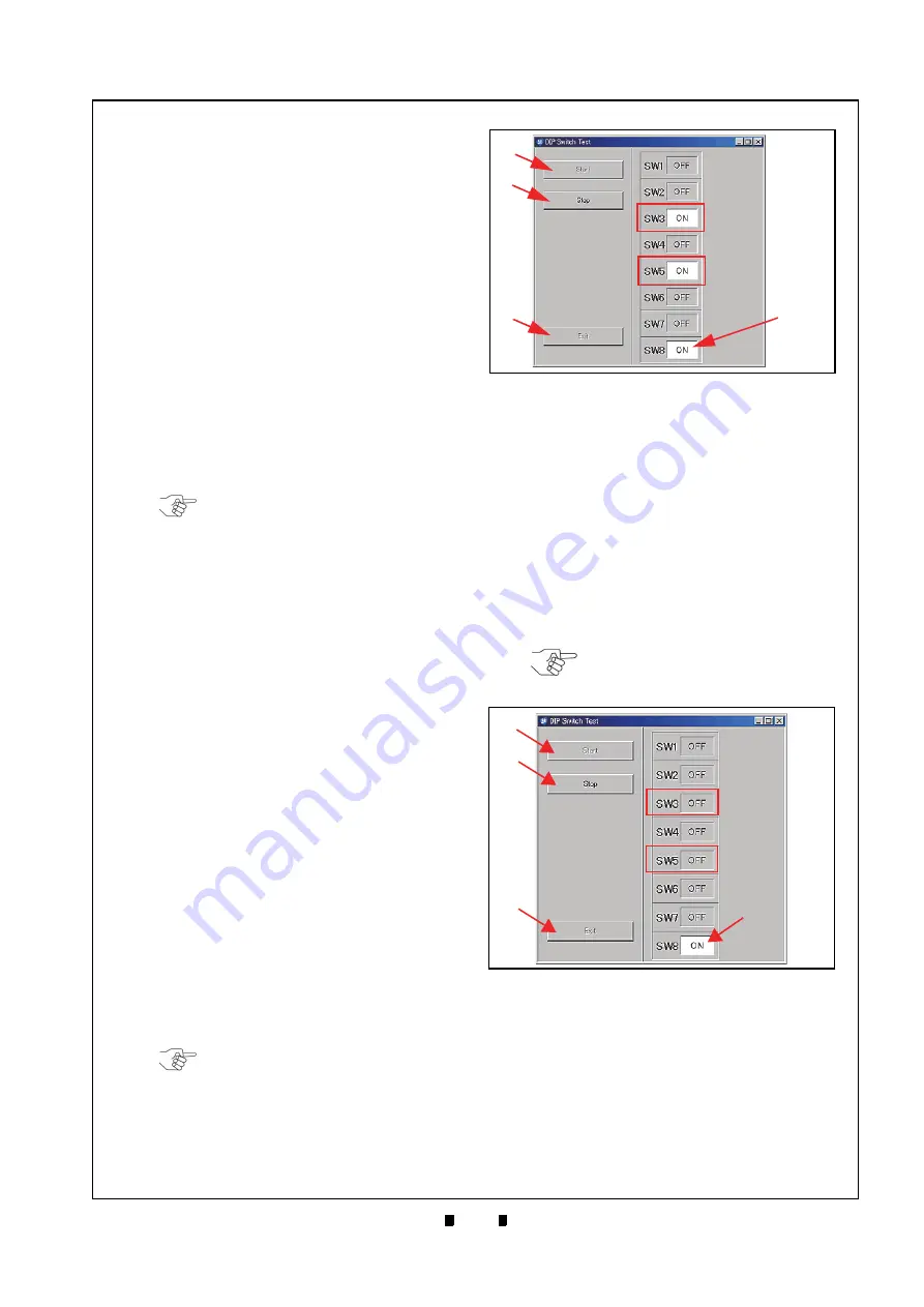
DIP Switch ON/OFF Test
Perform the following steps to test the 8-Position
DIP Switch ON/OFF Functions:
1. Turn the iVIZION Power Switch to
OFF
.
2. Remove the Transport Unit from the iVIZION
Unit’s upper Section.
3. Set the desired DIP Switches being tested to
ON
and set DIP Switch #8 to
ON
. DIP Switch #8 will
always be set to ON during all remaining Switch
Tests being performed (The Figure 6-60 example
shows DIP Switch #3 and #5, plus DIP Switch #8
all set to
ON
).
4. Launch
the
“
Test Item Select
” Screen (Refer to
“PC Performance Test Preparation” on page 6-11
of this Section).
5. Click on the “
DIP Sw ON/OFF Test
” Screen But-
ton (Review Figure 6-53
i
) to begin the DIP
Switch ON/OFF Test.
6. Click on the “
Start
” Screen Button (Figure 6-60
a
). The tested DIP Switch condition will be indi-
cated on the Screen similar to that shown in Fig-
ure 6-60. Make sure the desired DIP Switch
Number is shown as “
ON
”.
7. Set the desired DIP Switch to
OFF
example = DIP Switch #3 and #5).
8. Make sure the desired DIP Switch Number is
“
OFF
”. (If DIP Switch #3 and #5 were set during
a previous procedure, the Screen will indicate
“ON” in each Field Window related to their DIP
Switch Number).
9. Click on the “
Stop
” Screen Button (Figure 6-61
b
)
to end the DIP Switch ON/OFF Test.
10. Click on the “
Exit
” Screen Button (Figure 6-61
c
)
to return to the “
Test Item Select
” Screen.
11. Turn the iVIZION Power Switch
OFF
.
12. Place the Transport Unit onto the Frame.
NOTE: If the intent is to perform other
tests, close all of the Screens open on
the PC, and turn the iVIZION Power
Switch OFF; then, Turn the iVIZION
Power Switch back ON, and begin the
Performance Test Procedures over
again.
NOTE: If DIP Switch #3 and #5 were
set during a previous procedure, the
Screen will indicate “ON” in each Field
Window related to their DIP Switch
Number.
DIP Switch ON/OFF Test Screen 1
Figure 6-60
DIP Switch ON/OFF Test Screen 1
a
b
c
SW8 is
Performance
During a
Always “ON”
Test
NOTE: If it is necessary to perform
another test, make sure that DIP
Switch No.8 is still set to ON.
Figure 6-61
DIP Switch ON/OFF Test Screen 2
Figure 6-61
DIP Switch ON/OFF Test Screen 2
a
b
c
SW8 is Always
Performance Test
“ON” During a


