Pro I: Digital-I/O- and Counter Modules
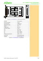
Pro-CNT-16/16 Rev. A
ADwin
112
ADwin-Pro
Hardware, manual version 2.9, June 2006
5.8.10 Pro-CNT-16/16 Rev. A
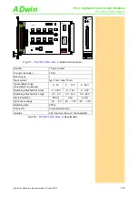
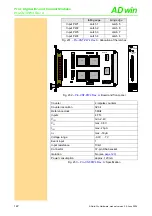
To this module you find an improved successor module
(see
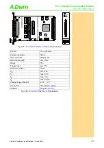
The counter module
has 16 counters (16 bit). All count
rates can be loaded into the register with a single
ADbasic
command so that
all counter values can be latched simultaneously. It is also possible to latch the
counters individually. With a rising edge of a TTL pulse the 16-bit counter incre-
ments by one The counter can be cleared by software command.
The count rate can be derived from the difference of two successive readings
of the latch.
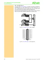
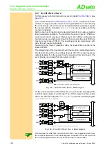
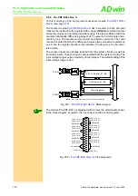
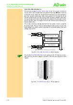
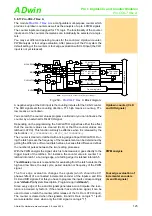
Fig. 211 –
: Block diagram
The module
is equipped with 16 times the components
shown in the block diagram; exception: the event input and the control register.
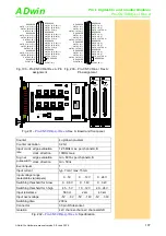
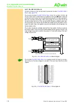
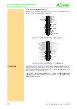
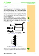
Fig. 212 –
: Pin assignment
NOTE:
Only Counter #1 is shown for clarity of the schematic.
Control Registers
16 bit Counter #1...#16
16 bit Latch #1...#16
CLK
EN
CLR
ADwi
n
-P
ro
bus
CLK #n
EVENT
10k
10k
CNTR 9 CLK
CNTR 13 CLK
CNTR 10 CLK
CNTR 14 CLK
CNTR 11 CLK
CNTR 15 CLK
CNTR 12 CLK
CNTR 16 CLK
DGND
EVENT IN
RESERVED
CNTR 1 CLK
CNTR 5 CLK
CNTR 2 CLK
CNTR 6 CLK
CNTR 3 CLK
CNTR 7 CLK
CNTR 4 CLK
CNTR 8 CLK
RESERVED
DGND
+5V, <100mA (unfused)
DGND
19
18
17
16
15
14
13
12
11
10
9
8
7
6
5
4
3
2
1
37
36
35
34
33
32
31
30
29
28
27
26
25
24
23
22
21
20
RESERVED
RESERVED
RESERVED
RESERVED
RESERVED
RESERVED
RESERVED

