ADwin-Pro
Hardware, manual version 2.9, June 2006
125
Pro I: Digital-I/O- and Counter Modules
Pro-CO4-T Rev. A
ADwin
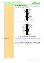
5.8.17 Pro-CO4-T Rev. A
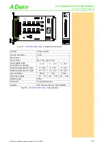
The module
is a configurable multi-purpose counter which
provides 4 up/down counters as well as the analysis of up to 4 PWM signals.
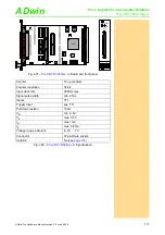
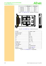
The counter inputs are designed for TTL logic. The functionality of the counter
inputs and of the counters themselves can individually be selected via regis-
ters.
You may set different operating modes for the counters: Up/down counter,
PWM analysis or four edge evaluation. After power-up of the Pro system the
default setting of the counters is four edge evaluation with CLR input (the CLR
input is not yet released).
Up/down counter (CLK
and DIR signals)
A negative edge at the CLK input is the counting impulse for the 32-bit counter.
The DIR signal sets the counting direction, TTL high means a count-up, TTL
low means a count-down.
You can latch the counter values program-controlled or you can influence the
counter by an external CLR/LATCH signal.
Depending on the programming the CLR/LATCH signal has either the effect
that the counter values are cleared (CLR) or that the counter values are
latched (LATCH). This function will only be effective when it is released by the
instructions
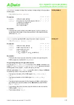
CO4_CLEARENABLE()
or
CO4_LATCHENABLE()
.
The counter is cleared or latched with a rising adge at input CLR/LATCH. Dur-
ing the latch process the frequency of the measurement can be determined by
getting the difference of two read latch values, because this difference defines
the number of pulses between the two reading processes.
PWM analysis
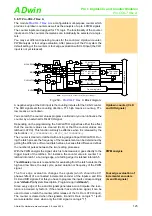
With the PWM analysis the signal, which is to be measured, goes directly to the
trigger inputs of the latches. For instance, the counter value in counter 1 is
latched into latch 1 at a rising edge, at a falling edge it is latched into latch 5.
The
ADbasic
process is responsible for evaluating from the latch contents the
high and low times, the duty cycle, period duration or frequency of the PWM
signal.
Four edge evaluation of
incremental encoders
(A- and B-signals)
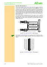
The four edge evaluation changes the signals (which should be 90°
phase-shifted) of a connected incremental encoder at the inputs a and B to
CLK and DIR signals. For this you have to program the inputs correspondingly
(see "
ADwin-Pro
System Description, Programming in
ADbasic
").
Since every edge of the a and B signals generates a count impulse, the reso-
lution is increased by factor 4. If the encoder has a reference signal, it can be
used to clear or latch the counter (after release of the CLR or LATCH input).
The counter is cleared when the signalsA, B and CLR are on logic "1" (soft-
ware-selectable: clear, when only the CLR signal is on logic "1").
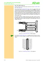
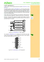
Fig. 239 –
: Block diagram
32 bit Counter
#1...#4
32 bit Latch
#5...#8
Control registers
32 bit Latch
#1...#4
CLK
EN
CLR
DIR
DIR
32 bit Latch
#9...#12
CO4_CLEAR
CO4_LATCHENABLE
CO4_CLEARENABLE
CO4_SETMODE
CNT_LATCH
CO4_SET_LATCHMODE
CO4_SETMODE
CO4_SET_LATCHMODE
G
40 MHz
CNT_ENABLE
ADw
in
-P
ro
bu
s
A/CLK/PWM
B/DIR
CLR/LATCH
EVENT
10k
10k
10
k
10
k
NOTE:
Only Counter #1 is shown for clarity of the schematic.


