Pro I: Digital-I/O- and Counter Modules
Pro-Comp-16 Rev. A
ADwin
138
ADwin-Pro
Hardware, manual version 2.9, June 2006
5.8.23 Pro-Comp-16 Rev. A
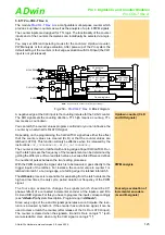
provides 16 input channels with a com-
parator each. The analog signals are acquired parallel and converted with a
10-bit resolution. Depending on switching thresholds, which are separately
adjustable by software for each channel, digital signals are generated from
these measurement values (1/0).
Fig. 261 –
: Block Diagram
The input voltage range of the module is between -2V…+8.23V, other voltage
ranges on request. The signals are acquired with 20MHz per channel.
Providing information
Information about the acquired signals is available per software:
– The digital signals (1/0) of all input channels
– The current converted measurement values
– The maximum and minimum of the acquired measurement values
– The last 1024 measurement values of 2 selected channels
– The digital signals (1/0) of measurement differences
After all measurement values have been acquired they are evaluated
quasi-differential, which means that for all 8 channel pairs (1/2, 3/4, ...,
15/16) the differences of the measurement vaues is calculated. Depend-
ing on the switching thresholds, digital signals (1/0) are generated from
these differences, which can be selected via software.
Fig. 262 –
: Pin assignment
Comp.
Attenuator
InAmp
+
-
V
IN1
V
OUT1
Comp.
Attenuator
InAmp
+
-
V
IN16
V
OUT16
V
T+
V
T-
t
V
IN1
V
T+
V
T-
t
V
IN16
t
V
OUT1
t
V
OUT16
RESERVED
INPUT 0
INPUT 1
INPUT 2
INPUT 3
INPUT 4
INPUT 5
INPUT 6
INPUT 7
INPUT 8
INPUT 9
INPUT 10
INPUT 11
INPUT 12
INPUT 13
INPUT 14
INPUT 15
DGND
RESERVED
DGND
19
18
17
16
15
14
13
12
11
10
9
8
7
6
5
4
3
2
1
37
36
35
34
33
32
31
30
29
28
27
26
25
24
23
22
21
20
DGND


