Pro I: Digital-I/O- and Counter Modules
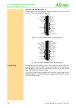
Pro-CO4-I Rev. A
ADwin
128
ADwin-Pro
Hardware, manual version 2.9, June 2006
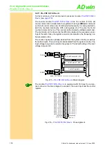
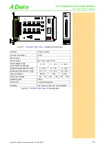
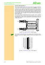
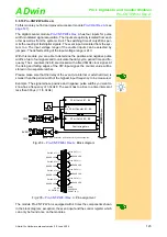
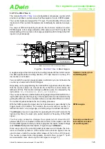
Fig. 245 –
: Board and front panel
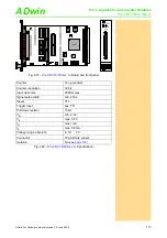
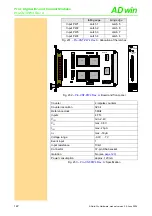
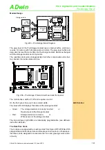
Fig. 246 –
: Specification
1
Counter
4 multi purpose counters
Counter resolution
32 bit
Event inputs
1
Reference clock
40MHz (100ppm)
Clock frequency four edge evaluation 5MHz max. (at 90° phase shift of the
signals)
Clock frequency up/down counter
10MHz max.
Reference frequency PWM analysis
40MHz
Input current
typ. 7mA / max. 15mA
input voltage range
(selectable via jumpers)
0…5V
0 … 12V
0…24V
reliable switching threshold
for 0
(low)
0…0.8V
0…1.6V
0…3.2V
reliable switching threshold
for 1
(high)
4.5…5V
10…12V
20…24V
Series resistor
510
Ω
1.51k
Ω
3.02k
Ω
Input over-voltage
8V
16V
30V
Negative voltage
-5V for all ranges
Switching time
100ns
Isolation
42Vchannel-channel / channel-GND
Connector
37-pin DSub socket
Power consumption
approx. 200mA
1. A low/high signal will reliably be recognized in the indicated voltage ranges. But the switch-
ing process can also be effected outside these voltage ranges.
19DIOCNT201
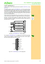
A0 A1 A2 A3 A4 A5 A6 A7
OCX
40MHz
AT17LV010
LM3940-3.3
XILINX
SPARTAN
XC2S150
LM3937-2.5
AD
M
706
AD
M
706
ON
DIP
1
2
3
4
5
6
7
8
7S
08B
HCPL-2631
19DIOCNTII01
74LS19
74LS19
74LS19
HCPL-2631
HCPL-2631
HCPL-2631
HCPL-2631
HCPL-2631
HCPL-2631
HCPL-2631
HCPL-2631
20/1
5V
12V
24V
5V
12V
24V
5V
12V
24V
5V
12V
24V
5V
12V
24V
5V
12V
24V
5V
12V
24V
5V
12V
24V
5V
12V
24V
5V
12V
24V
5V
12V
24V
5V
12V
24V
5V
12V
24V
5V
12V
24V
5V
12V
24V
5V
12V
24V
11/29 10/28 9/27 8/26 7/25 6/24 5/23 4/22
5V
12V
24V
19/37 18/36 17/35 16/34 15/33 14/32 13/31 12/30
CO4-I
COUNTER
INPUT

