Pro I: Signal Conditioning and Interface Modules
Pro-CAN-x Rev. A
ADwin
172
ADwin-Pro
Hardware, manual version 2.9, June 2006
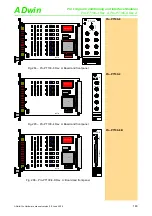
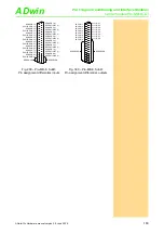
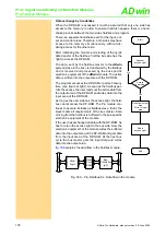
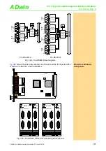
Abb. 304 – Pro-CAN: Pin assignment
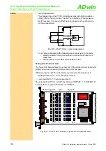
Abb. 305 – Pro-CAN-LS: Pin assignment
Power supply
(Low speed only)
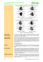
The "low speed" version Pro-CAN-x-LS requires an external power supply of
12V DC to run the CAN controller. The module Pro-CAN-2-LS needs a power
supply for each controller separately.
Bus termination
(High speed only)
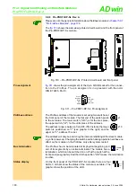
If the CAN module functions as the physical termination of a high-speed CAN
bus, it must be terminated with a 120
Ω
resistor (only the first or the last CAN
node). If a termination is necessary, move the DIP switch (Rev. A2, see
) upward; when using the module revision A1 set the jumper to the left
position (ON). CAN nodes, which are not positioned in an end-location, must
not be terminated.
Message Management
Identifier
The CAN controller identifies messages by an identifier; these are parameters
in a defined bit length. The parameters 0...2
11
-1 or 0...2
29
-1 result from the bit
length.
Message objects
The controller stores each message (incoming or outgoing) in one out of 15
message objects. The message objects can either be configured to send or to
receive messages. Message object 15 can only be used to receive messages.
After initializing the CAN controller all message objects are not configured.
Each message object has an identifier, which enables the user to assign a
message to a message object.
Transferring messages
In
ADbasic
a message is transferred to a message object using the array
can_msg
[][]
, which can receive 8 data bytes plus the amount of data bytes
(9 elements). When reading a message from the message object it can also be
transferred to the array
can_msg
[][]
.
CAN-1
CAN-2
Connector 1.1 (male)
Connector 1 (male)
Connector 1.2 (female)
Connector 2 (male)
CAN-1-LS
CAN-2-LS
Connector 1.1 (male)
Connector 1 (male)
Connector 1.2 (female)
Connector 2 (male)
1
2
3
4
5
6
7
8
9
RESERVED
CAN(-)
GND
GND
CAN(+)
RESERVED
RESERVED
1
2
3
4
5
6
7
8
9
RESERVED
CAN(-)
GND
GND
CAN(+)
RESERVED
RESERVED
5
4
3
2
1
9
8
7
6
GND
CAN(-)
RESERVED
CAN(+)
GND
RESERVED
RESERVED
1
2
3
4
5
6
7
8
9
RESERVED
CAN(-)
GND
GND
CAN(+)
RESERVED
RESERVED
1
2
3
4
5
6
7
8
9
RESERVED
CAN(-)
GND
GND
CAN(+)
RESERVED
+12V (INPUT)
RESERVED
1
2
3
4
5
6
7
8
9
RESERVED
CAN(-)
GND
GND
CAN(+)
RESERVED
+12V (INPUT)
RESERVED
5
4
3
2
1
9
8
7
6
GND
CAN(-)
RESERVED
+12V (INPUT)
RESERVED
CAN(+)
GND
RESERVED
1
2
3
4
5
6
7
8
9
RESERVED
CAN(-)
GND
GND
CAN(+)
RESERVED
+12V (INPUT)
RESERVED


