Pro I: Analog Input and Output Modules
Pro-AO-16/8-12 Rev. A
ADwin
92
ADwin-Pro
Hardware, manual version 2.9, June 2006
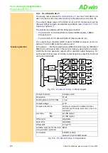
Input voltage range
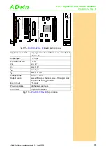
In figure
all (allowed) possibilities to adjust the jumpers for setting the input
voltage range are listed.
The potentiometers UPO, B and G are used for an accurate adjustment of gain
and offset (
). The jumpers as well as the potentiometers for setting the
input voltage range can be found on the lower part of the module.
If nothing else has been said on ordering the module, the voltage range is set
to ±10V. After every jumper setting you have to recalibrate the ADC, in order
to assure correct measurement results. The individual steps are described in
.
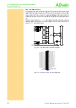
Output voltage range
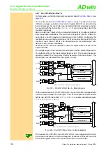
all possible jumper settings for the output voltage range are listed.
The potentiometers
O1-4
for the outputs 1…4 and
O5-8
for the outputs 5…8
or respectively,
G1-4
and
G5-8
) are used for an accurate adjustment
of gain and offset.
The jumpers as well as the potentiometers for setting the output voltage range
can be found on the lower part of the module.
If nothing else has been said on ordering the module, the voltage range is set
to ±10V. After every jumper setting you have to recalibrate the DAC, in order
to assure correct measurement results. The individual steps are described in
chapter 6.3.1 "Calibration per Software"
.
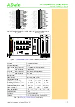
Voltage range
Jumper set-
tings
±5V bipolar
±10V
(default)
0…10V
Fig. 167 –
: Jumper settings for the
input voltage range
UNI
BIP
10V
20V
UNI
BIP
10V
20V
UNI
BIP
10V
20V
Potenti-
ometer
Adjustment of
Gain
Gain factor
BPO
Offset (bipolar setting)
UPO
Offset (unipolar setting)
Fig. 168 –
Function of the potentiometers
for the inputs
Voltage range
Jumper set-
tings
±5V bipolar
±10V
(default)
0…10V
Fig. 169 –
: Jumper settings for the
output voltage range
Potenti-
ometer
Adjustment of
G1-4
G5-8
Gain factor
O1-4
O5-8
Offset
Fig. 170 –
Function of the potentiometers
for the outputs


