42
①
Area sensor
③
Area sensor
HBM-201 OUT1
(
Roller surface standby output
)
HBM-201 OUT2
(
Carrier wheel surface standby output
)
③
Area sensor
1
2
3
4
5
ON
OFF
ON
OFF
ON
OFF
ON
OFF
ON
OFF
ON
OFF
ON
OFF
HBM-201 INPUT2
(
Carrier wheel surface switch input
)
HBM-201 INPUT1
(
Roller surface switch input
)
RUN
STOP
RUN
STOP
ON
OFF
MA
IB-P02F-P-FT
MB
RemoteOUT 2
RemoteIN 2
RemoteOUT 1
SensorAlarm A
SensorAlarm B
SensorA_SEN
SensorB_SEN
※
※
Switch the transfer surface after an interval of 50ms.
6.
Control/Operation
F-RAT-NX75 Annex User Manual for IB-P02F-P-FT
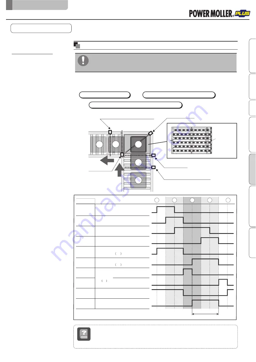
The following time chart is an example.
When in use, control the number of sensors, and/or determine how to place/control sensors
depending on your operation.
Zone sensor for the discharge conveyor
F-RAT zone sensor
Zone sensor for the load conveyor
Time chart example
Tray position
Roller transfer MDR
M2
Carrier wheel transfer MDR
M1
Drive switching
MDR
M3
F-RAT zone sensor
①
Area sensor
(
Carrier wheel discharge direction
)
Zone sensor for the load conveyor
5
2
1
4
3
Basic operation
(example)
V-ribbed pulley
Operation by loading through
roller transfer and discharging
through carrier wheel transfer
Program example
Program example
6-3.
Program example
■
Do not load trays from the roller transfer MDR direction while the carrier
wheel status is output (signal input to SensorAlarm B on IB-P02F-P-FT).
Failure to follow this could result in damage to trays, and malfunction.
*1
*1
*2
*2
*1
*1
*2
Zone sensor
Term
A sensor to detect the existence of trays within the zone
Area sensor
A sensor to detect load and discharge of trays
Loading through roller transfer
⇒
⇒
Discharging through carrier wheel transfer
Standing ready on the roller surface after discharge ends
Advanced preparation
Product check
Wiring
Maintenance/Inspection
Appendix
IB-P02F-P-FT settings
Control/Operation
Original notice - U1.1


