31
■
Spaces (blank) cannot
be used.
■
Only alphanumeric
characters can be used.
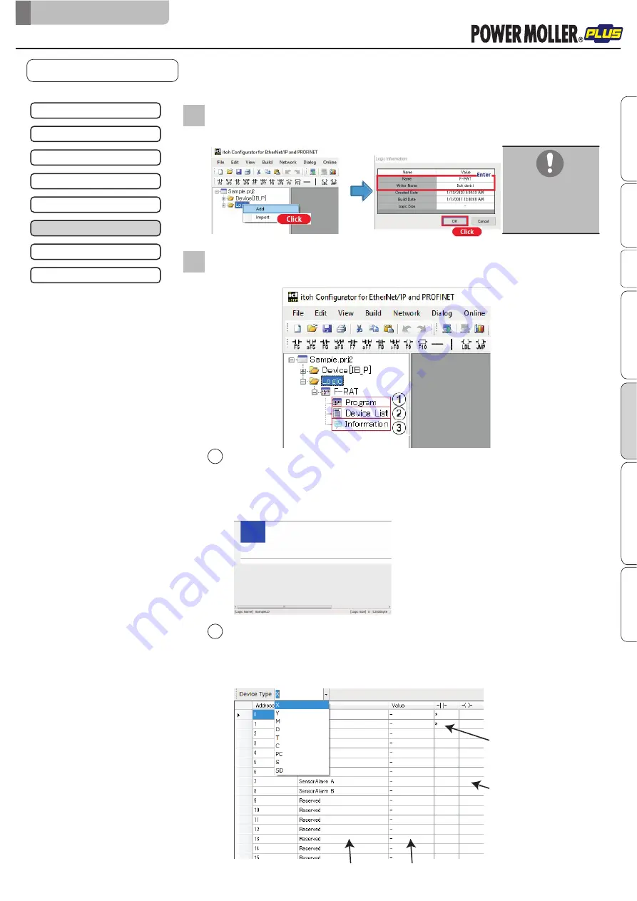
Select ‘Logic’ on the project tree window, and right-click “add” to select.
Enter the logic name and creator’s name in Logic Information.
2
The name of the logic information is displayed under “Logic” on the project tree
window, and “Program”, “Device List”, and “Information” are likewise displayed.
3
Program window
Double-click ‘Program’ to display the program window as below. Contacts will be entered at the
cursor position.
The ladder logic name is displayed at the lower left of the window, and the ladder logic size is
displayed at the lower right of the window.
The ladder logic size will be updated per build.
Device List window
Double-click ‘Device List’ to display the program window as below.
Select X, Y, M, D, T, C, PC, S, or SD for ‘Device Type’ to display the list of selected contacts.
Comments can be entered in the Comment field. The current value will be displayed in the Value
field during ladder monitoring.
Description of each window
Comment field
Value field
Contact usage status
(“
*
” will be displayed when used)
Output usage status
(“
*
”will be displayed when used)
Creating the ladder logic
6.
Control/Operation
2
1
F-RAT-NX75 Annex User Manual for IB-P02F-P-FT
Setting the IP address
↓
Creating the project file
↓
Registering IB-P02F-P-FT to be used
↓
IB-P02F-P-FT property settings
↓
Writing properties
Complete
↓
Creating the IB-P02F-P-FT ladder logic
↓
Writing the ladder logic
↓
Advanced preparation
Product check
Wiring
Maintenance/Inspection
Appendix
IB-P02F-P-FT settings
Control/Operation
Original notice - U1.1


