CS Context Overview
183
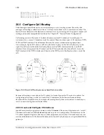
interface, during a call setup the first codec listed in the H.323 gateway which matches with the
remote SmartNode is taken. For information how to configure the codecs for a H.323 connection
refer to Chapter 25, “Gateway Configuration”.
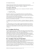
In H.323 there are two call signaling methods, 'direct call signaling' and 'gatekeeper routed call
signaling'. Direct call signaling works in the same way as ISoIP. Gatekeeper routed call signaling
uses a gatekeeper to find the destination address. For examples and information on how to configure
direct call signaling on H.323 voice connections, refer to Chapter 21, “CS Interface Configuration”
.
To
configure gatekeeper routed call signaling on H.323 voice connections refer to Chapter 25, “Gateway
Configuration”.
Q.931 tunneling is able to support ISDN services and Q.SIG over an IP network. In ISoIP Q.931
tunneling is always enabled. To configure Q.931 tunneling on a H.323 connection, refer to Chapter
25, “Gateway Configuration”.
20.11 Activate CS Context Configuration
After configuring the CS context and all its components the configuration must be activated. This
includes binding the PSTN interfaces to the ISDN ports and enabling the gateways, ISDN ports and
the CS context.
In order to become functional, each PSTN interface must be bound to one or more ISDN ports from
which it receives incoming calls and to which it forwards outgoing calls. Note that there is a
difference between IP interfaces and Ethernet ports. In the IP context the
ethernet port is bound
to
the IP interface, in the CS context the
PSTN interface is bound
to the ISDN port! After binding to
become active the ISDN port must be enabled.
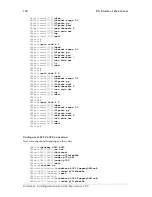
To bind the PSTN interfaces to ISDN ports refer to Chapter 21, “CS Interface Configuration”, and to
enable the ISDN ports refer to Chapter 24, “ISDN Port Configuration”. Likewise the ISoIP or H.323
gateway must be enabled. Additionally the H.323 gateway must be bound to a specific IP interface.
For more information refer to Chapter 25, “Gateway Configuration”.
In order to become active the CS context must be enabled. When recovering from the shutdown
status, the CS context and Session Router configuration is checked and possible errors are indicated.
The Session Router debug monitor can be enabled to show the loading of the CS context and Session
Router configuration. SmartWare offers a number of possibilities to monitor and debug the CS
context and session router configurations. For example the Session Router debug monitor enables
you follow the sequence of tables and functions examined by the Session Router for each call setup.
Refer to Chapter 27, “VoIP Debugging” for an introduction to the configuration debugging
possibilities in SmartWare.
Note:
You can modify the configuration at runtime, but changes will not be active immediately. It is
not necessary to shutdown the CS context prior to making any configuration changes, but if the CS
context is not activated with the command
no
shutdown
the newly created or changed configuration
is not loaded!
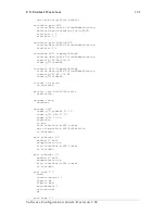
There are several possibilities to show the actual CS context configuration. Note that some of the
show commands display only the actual configuration. It could be that you have changed your
configuration and it is not displayed because the configuration is reloaded. For more information on
the show command refer to the respective configuration chapters or to the Chapter 27, “VoIP
Debugging”.
Software Configuration Guide, Revision 1.03


