Link Scheduler Configuration
117
Procedure
Creating an access control list for tagging web traffic from the single source host at a certain IP
address.
Mode
Configure
Command
Purpose
Step 1
node
(cfg)#profile acl
name
Creates a new access control list profile
named
name
Step 2
node
(pf-acl)[
name
]#permit ip host
ip-
address
any cos
cos-name
Creates an IP access control list entry
that permits access for host at IP
address
ip-address
, and specifies that
packets matched by this rule belong to
the class of service
cos-name
.
Step 3
node
(pf-acl)[
name
]#permit ip any any
Creates an IP access control list entry
that permits IP traffic to or from all IP
addresses.
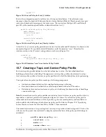
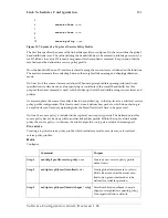
Example: Defining the Access Control List Profile
In the example below a new access control list profile named
Webserver
is created. In addition an IP
access control list entry that permits access for host at IP address
172.16.1.20
, and specifies that
packets matched by this rule belong to the class of service
Web
is added. Finally an IP access control
list entry that permits IP traffic to or from all IP addresses is added to the access control list.
SN(cfg)#
profile acl Webserver
SN(pf-acl)[Webserv~]#
permit ip host 172.16.1.20 any cos Web
SN(pf-acl)[Webserv~]#
permit ip any any
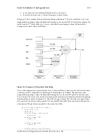
After packet classification is done using access control lists to tag packets to a certain class, as
introduced in the preceding chapter, the link arbiter needs rules defining how to comply with all the
traffic classes. For that purpose the network administrator creates a service policy profile. The service
policy profile is in particular used to define how the link arbiter has to share the available bandwidth
among several traffic classes on a certain interface.
The following sections describe methods to assign and share bandwidth on an IP interface.
15.6 Assigning Bandwidth to Traffic Classes
To manage the access link bandwidth basically means to determine the order in which packets of the
different classes are served.
Priority
One way of ordering packets is to give priority to one class and to serve the others classes when the
first has nothing to send. SmartWare uses the priority scheme to make sure that voice packets
generated by the SmartNode will experience as little delay as possible. But we can only give the
voice packets such an exclusive treatment because we know that they will not use up the whole
bandwidth and that they will leave enough space for the lower priority classes.
Software Configuration Guide, Revision 1.03


