


Removing a SAN768B from the cabinet
If you need to remove a SAN768B chassis from a cabinet to move it to a new
location, follow the instructions below to remove the chassis, and then follow the
installation instructions (“Installing a SAN768B in a cabinet” on page 14) to install
the chassis in the new cabinet. If you are replacing the chassis, follow the complete
instructions in “Removing and replacing the chassis” on page 109.
Attention:
Refer to “Safety notices and labels” on page xv before starting any
service procedure. Due to the weight of the product, this procedure requires a lift
tool. See “Ordering the lift tool” on page 12 for information on ordering the lift
tool.
Step 1 through step 5 describes how to use the lift tool (PN 09P2481) and the
24–inch load plate (PN 11P4369) to remove a SAN768B from the cabinet. Step 6
through step 17 on page 29 describes how to remove the bridge tool (PN 18P5855)
from the cabinet.
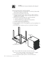
Perform the following steps to remove a SAN768B:
1.
Assemble the lift tool if it is not assembled. The assembly and disassembly
instructions are included with the lift tool.
2.
Remove both power cords from the SAN768B.
3.
Optionally, remove the power supplies and blower assemblies to reduce the
weight.
4.
Remove the chassis door from the chassis. See “Removing the chassis door
and cable management comb” on page 18.
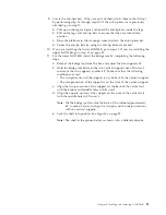
5.
Remove the three 10-32 x 5/8 in. Phillips panhead screws with washers on
each side. See Figure 9 on page 23 for the location of the screws.
6.
If you are replacing the lower SAN768B, go to step 7. If you are replacing the
upper SAN768B, go to step 8.
7.
Install the bridge tool by completing the following steps:
a.
Remove the bridge tool from its box and adjust the two supports 45°.
b.
Hold the bridge tool between the two vertical supports near EIA unit 3.
c.
Move the two supports another 45°. Make sure that the following
conditions are met:
v
The two-pin section of the support is on the back of the vertical support.
v
The one-pin section of the support is on the front of the vertical support.
d.
Align the two-pin section of the support on the back of the vertical rail
with the bottom and middle holes in EIA unit 3.
e.
Align the one-pin section of the support on the front of the vertical rail
with the middle hole in EIA unit 1.
Note:
Tilt the bridge tool towards the back of the cabinet approximately
45° to make it easier to align the two-pin and one-pin sections with
the vertical support.
f.
Lock the shelf into position.
8.
For the upper SAN768B, install the bridge tool by completing the following
steps:
a.
Remove the bridge tool from its box and adjust the two supports 45°.
b.
Hold the bridge tool between the two vertical supports near EIA unit 20.
28
SAN768B Installation, Service, and User Guide
Содержание SAN768B
Страница 2: ......
Страница 8: ...vi SAN768B Installation Service and User Guide ...
Страница 12: ...x SAN768B Installation Service and User Guide ...
Страница 14: ...xii SAN768B Installation Service and User Guide ...
Страница 16: ...xiv SAN768B Installation Service and User Guide ...
Страница 28: ...xxvi SAN768B Installation Service and User Guide ...
Страница 32: ...xxx SAN768B Installation Service and User Guide ...
Страница 42: ...10 SAN768B Installation Service and User Guide ...
Страница 62: ...30 SAN768B Installation Service and User Guide ...
Страница 78: ...46 SAN768B Installation Service and User Guide ...
Страница 100: ...68 SAN768B Installation Service and User Guide ...
Страница 154: ...122 SAN768B Installation Service and User Guide ...
Страница 178: ...146 SAN768B Installation Service and User Guide ...
Страница 184: ...152 SAN768B Installation Service and User Guide ...
Страница 202: ...170 SAN768B Installation Service and User Guide ...
Страница 207: ......
Страница 208: ... Part Number 45W8666 Printed in USA GA32 0574 05 1P P N 45W8666 ...