


clip nuts (
D
) or retainer nuts (
F
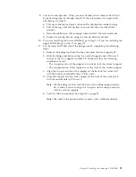
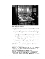
) installed on the rails earlier. Tighten the
screws to a torque of 37 cm-kg (32 in-lb). See Figure 9 for the approximate
location of the screws.
Note:
Do not use the top or bottom holes of the SAN768B mounting brackets
because the screw heads will interfere with the chassis door.
21.
Reinstall the cable management comb, if it was removed (see “Removing and
installing a cable management comb” on page 70).
22.
If ICL cables will not be used, ensure that the ICL sockets in the core switch
blades have EMI plugs inserted.
23.
Reinstall the chassis door. Align the door with the chassis and push it into
place, as shown in Figure 10 on page 24 and Figure 11 on page 25.
b768ig031
Figure 9. Attaching the port side of the chassis to the cabinet rails
Chapter 2. Installing and removing a SAN768B
23
Содержание SAN768B
Страница 2: ......
Страница 8: ...vi SAN768B Installation Service and User Guide ...
Страница 12: ...x SAN768B Installation Service and User Guide ...
Страница 14: ...xii SAN768B Installation Service and User Guide ...
Страница 16: ...xiv SAN768B Installation Service and User Guide ...
Страница 28: ...xxvi SAN768B Installation Service and User Guide ...
Страница 32: ...xxx SAN768B Installation Service and User Guide ...
Страница 42: ...10 SAN768B Installation Service and User Guide ...
Страница 62: ...30 SAN768B Installation Service and User Guide ...
Страница 78: ...46 SAN768B Installation Service and User Guide ...
Страница 100: ...68 SAN768B Installation Service and User Guide ...
Страница 154: ...122 SAN768B Installation Service and User Guide ...
Страница 178: ...146 SAN768B Installation Service and User Guide ...
Страница 184: ...152 SAN768B Installation Service and User Guide ...
Страница 202: ...170 SAN768B Installation Service and User Guide ...
Страница 207: ......
Страница 208: ... Part Number 45W8666 Printed in USA GA32 0574 05 1P P N 45W8666 ...